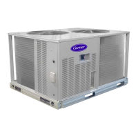
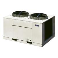
EasyManua.ls Logo

Carrier 38AUQA/B07 - User Manual

Carrier 38AUQA/B07
52 pages
Print Icon
To Next Page IconTo Next Page
Loading...
1
38AUQ
Heat Pu mp Condensing Units
60 Hz
with Puronr (R---410A) Refrigerant
Sizes: 07, 08 and 12
Installation, Start---Up
and Service Instructions
CONTENTS
SAFETY CONSIDERATIONS 2....................
INSTALLATION GUIDELINES 3..................
Rated Indoor Airflow (cfm) 3.....................
INSTALLATION 7 -- 17...........................
Step 1 -- Plan for Unit Location 7..................
Step 2 -- Complete Pre--Installation Checks 8.........
Step3–PrepareUnitMounting Support 8...........
Step 4 -- Rig and Mount the Unit 8.................
Step 5 -- Complete Refrigerant Piping Connections 8...
Step 6 -- Install Accessories 12....................
Step 7 -- Complete Electrical Connections 12.........
Step 8 -- Wind Baffles for Low Ambient Control 17...
PRE-START-UP 18...............................
System Checks 18..............................
Turn On Crankcase Heaters 18....................
Preliminary Charge 18...........................
START--UP 18 -- 27..............................
38AUQ Units 18...............................
OPERATING SEQUENCE 28......................
Indoor (Supply) Fan 28..........................
Cooling Unit Without Econom izer --
Single Stage Units 28............................
Cooling Unit Without Econom izer --
Two--Stage Units 28.............................
Fan Cycling 28.................................
Cooling Unit With Economi zer 28.................
Defrost Cycle 28...............................
Supplemental Heating/Emergency Heating 29........
Cooling and Heating Shutdown 29.................
ROUTINE SYSTEM MAINTENANCE 30............
Quarterly Inspection
(and 30 days after initial start) 30..................
SERVICE 31 - 44................................
Refrigeration System 31.........................
Compressor Oil 31..............................
Servicing Systems on Roofs
with Synthetic Materials 31.......................
Liquid Line Filter Driers 31.......................
Filed Refrigerant Access Ports 31..................
Outdoor Coil Metering Device s 31.................
Refrigerant System Pressure Access Ports 32.........
Compressor Protection 32........................
Crankcase Heater 32............................
Commercial Defrost Board 32.....................
Comfort Alert Diagnostic Module 40...............
Lubrication 42.................................
Outdoor Coil Maintenance and
Clea ning Recommendations 42....................
Service Parts 44................................
Fastener Torque Values 44........................
TROUBLESHOOTING 45.........................
APPENDIX A
Air Conditioner and Heat Pump with Puron
R
Quick Reference Guide 46........................
APPENDIX B
Wiring Diagram List 46..........................
APPENDIX C
Low Ambient Option Factory Installed 47.........
START--UP CHECKLIST 51-- 52...................
Question and Answer IconNeed help?

Do you have a question about the Carrier 38AUQA/B07 and is the answer not in the manual?

Overview

The Carrier 38AUQ Heat Pump Condensing Units are designed for use with Puron® (R-410A) refrigerant, operating at 60 Hz, and are available in 07, 08, and 12 sizes, corresponding to 6, 7.5, and 10 tons nominal capacity, respectively. These units are intended for installation with matching 40RUQ indoor sections.

Function Description:

The 38AUQ units function as heat pump condensing units, providing both cooling and heating capabilities. They utilize a scroll compressor (single or two-stage depending on the model) and are equipped with a Defrost Board (DFB) to manage defrost cycles in heating mode. A Comfort Alert Diagnostic Module (CADM) monitors compressor and system performance, providing diagnostic codes via flashing LEDs to assist in troubleshooting. Low ambient options are available, which include a Motormaster® solid-state head pressure control to regulate fan speed for optimal performance in cold weather.

Important Technical Specifications:

  • Refrigerant: Puron® (R-410A), operating at higher pressures than R-22 systems.
  • Nominal Capacity: 6, 7.5, and 10 tons.
  • Operating Weights: Ranging from 444 lbs (201 kg) for 6-ton units to 575 lbs (261 kg) for 10-ton units.
  • Outdoor Fans: Two fans per unit, 1/4 hp each, 22-inch diameter, 1100 rpm, providing 6,000 cfm total nominal airflow.
  • Outdoor Coil: Round Tube/Plate Fin (RTPF) type, with face areas ranging from 17.5 sq ft to 28.1 sq ft.
  • Pressurestat Settings:
    • High Cutout: 630 ±10 psig (4344 ±69 kPa), automatic reset at 505 ±20 psig (3482 ±140 kPa).
    • Low Cutout: 27 ±3 psig (186 ±21 kPa), automatic reset at 44 ±5 psig (303 ±35 kPa).
  • Piping Connections (ODS):
    • Vapor: 1-1/8 in. for 6 and 7.5-ton units, 1-3/8 in. for 10-ton units.
    • Liquid: 3/8 in. for 6-ton units, 1/2 in. for 7.5 and 10-ton units.
  • Electrical: Available in 208/230-3-60, 460-3-60, and 575-3-60 voltages.
  • Compressor Oil: Polyolester (POE) oil, which is highly hygroscopic.
  • Filter Drier: Factory-provided reversible filter drier with 100% molecular sieve grade XH-11 desiccant.
  • Maximum Allowable Line Length: 100 ft (30.5 m).

Usage Features:

  • Installation: Units are designed for overhead rigging. Minimum clearances for service and airflow must be observed (e.g., 36 inches for outdoor coil airflow, 42 inches for control box side).
  • Refrigerant Piping: Existing R-22 piping can be reused if in excellent physical condition, clean, and of appropriate size for R-410A's higher pressures. A bi-directional filter drier is required in the liquid line, located at the indoor unit near the TXV inlet. Liquid line solenoid valves are recommended for line lengths exceeding 75 ft (23 m) to prevent refrigerant migration.
  • Electrical Connections: Field wiring must comply with NEC and local codes. Units may have factory-installed or field-supplied disconnect switches. Convenience outlets (non-powered or unit-powered) are available for service.
  • Start-Up: A pre-start-up checklist ensures proper installation and charging. Crankcase heaters must be energized for 24 hours before compressor start-up to prevent oil dilution. For 3-phase units, compressor rotation must be verified to avoid damage. Refrigerant charge is adjusted in cooling mode only, using charging charts based on liquid line pressure and temperature.
  • Controls: The Defrost Board (DFB) manages cooling, heating, emergency heating, and defrost cycles. The Comfort Alert Diagnostic Module (CADM) provides real-time diagnostics for electrical and system-related failures via flashing LEDs.
  • Low Ambient Operation: Optional factory-installed low ambient control uses a Motormaster® solid-state head pressure control and a temperature sensor to regulate fan speed, allowing operation down to -20°F (-28°C). Wind baffles are required for these applications.

Maintenance Features:

  • Routine Inspection: Quarterly inspections are recommended for indoor and outdoor sections, including checking coil cleanliness, air filters, belt tension and condition, pulley alignment, fan shaft bearing tightness, condensate drain, blower motor amperage, fan motor mounting bolts, compressor mounting bolts, fan blade positioning, control box cleanliness, wiring terminal tightness, and refrigerant charge level.
  • Coil Cleaning: Routine cleaning of coil surfaces is essential. Surface-loaded fibers and dirt should be removed with a vacuum cleaner or soft brush, applied in the direction of the fins. Periodic low-velocity clean water rinses are beneficial, especially in coastal or industrial environments. Totaline® environmentally sound coil cleaner is recommended for thorough cleaning.
  • Filter Drier Replacement: The liquid line filter drier must be replaced whenever the refrigerant system is opened, using only factory-authorized components with XH-11 desiccant. Driers should be cut out, not unsweated, to prevent moisture and contaminants from entering the system.
  • Refrigerant Access Ports: Field service access to refrigerant pressures is provided via 1/4-in SAE Flare couplings with Schrader check valves.
  • Compressor Oil: POE oil is extremely hygroscopic; precautions must be taken to avoid exposure to the atmosphere. Special care is advised when servicing systems on roofs with synthetic materials to prevent oil spills.
  • Fan Motors: Outdoor fan motors have permanently lubricated sealed bearings and do not require lubrication.
  • Compressor: The compressor has internal limbered motor protection and overtemperature protection. The crankcase heater prevents refrigerant migration and oil dilution during shutdown.

Carrier 38AUQA/B07 Specifications

General IconGeneral
BrandCarrier
Model38AUQA/B07
CategoryHeat Pump
LanguageEnglish

Related product manuals