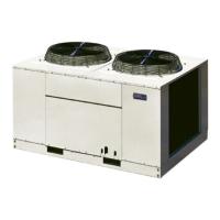
The Carrier 38AB,AD series are air-cooled condensing units, designed for installation, start-up, and service in various applications. These units range from 024 to 084 models, with varying dimensions and capacities.
Function Description:
These units are air-cooled condensing units, which are a key component in refrigeration and air conditioning systems. They are designed to dissipate heat from the refrigerant to the ambient air, thus facilitating the cooling cycle. The units are available in single and dual compressor configurations, offering flexibility for different cooling demands. They incorporate various control and safety features to ensure efficient and reliable operation.
Important Technical Specifications:
Dimensions (ft-in.):
- Length (A): 13-0 (for 38AD024-034), 12-10 1/16 (for 38AD044), 24-4 (for 38AB054-084)
- Width (B): Ranges from 3-11 3/4 to 6-0 3/4 depending on the model.
- Height w/o Legs (C): Ranges from 2-4 1/8 to 3-2.
- Leg Height (D): Adjustable, ranging from 1-0 or 2-0 to 1-8 or 2-4.
Connections (in.):
- Suction (ODM): 1-5/8 (for 38AD024-044, 38AB054-064), 2 (for 38AB084 - two connections).
- Liquid (ODM): 7/8 (all models).
Openings (in.):
- Suction (E): 2-1/2 (38AD024-034), 4 (38AD044), 5 (38AB054-084 - two connections for 38AB084).
- Liquid (F): 1-1/4 (38AD024-034), 1-5/8 (38AD044), 2-1/4 (38AB054-084).
- Control (4 holes) (G): 7/8 (all models).
- Power (H): 3-5/8 (38AD024-044), 3-5/8 (38AB054-064), 3-5/8 (38AB084 - two connections).
Electrical Data (3-Phase, 60-Hz):
- Voltage: Available in 200, 208, 230, 460, and 575 volts.
- Compressor Full Load Amps (FLA): Ranges from 28.6 to 165.0 depending on model and voltage.
- Compressor Locked Rotor Amps (LRA): Ranges from 120 to 636.
- Fan FLA: Ranges from 1.6 to 6.6.
- Max Fuse Amps: Ranges from 50 to 450.
- Compressor: Reciprocating Hermetic, 1750 rpm.
- Cylinders: 4 or 6, depending on model.
- Oil (pt): 14 or 19.
- Crankcase Heater: 125 Watts.
- Condenser Fans: Axial Flow, Direct Drive, 3 or 6 fans, 1140 rpm, 3/4 or 1 Hp each.
- Condenser Coil: Plate Fins, 3-row or 4-row (for 38AD044 and 38AB084).
- Refrigerant: R-22.
- Operating Charge (lb): Ranges from 28.0 to 132.0.
- Refrigerant Storage Capacity (lb): Ranges from 70 to 322.
Controls:
- Capacity Control: By one or two suction pressure actuated unloaders, each controlling two cylinders. Adjustable from 0 to 85 psig for load point, and 6 to 22 psig for pressure differential.
- Pressurestat: High cutout (375 psig), low cutout (29 psig for 38AD, 44 psig for 38AD024-034, 45 psig for 38AD044, 63 psig for 38AB).
- Oil Pressure Control: 5 Psi above suction pressure.
- Fan Cycling Thermostat: Opens at 70 F, closes at 75 F (No. 1); opens at 57 F, closes at 62 F (No. 2).
- Discharge Line Thermostat: Opens at 290 F, closes at 210 F.
- Safety Relief: Fusible Plug.
Usage Features:
- Rigging and Installation: Units can be lifted using eyebolts and washers. Skidded units can be slung, but the sling must not contact unit sides. Unskidded units should not be rolled on pipes or wooden pilings. Legs and gussets are provided for proper unit elevation and stability. Units 38AB054,064,084 require integration of two sections (compressor with coil, and coil only) by connecting refrigerant piping and electrical conduits.
- Air Flow: Requires overhead air space of 8-0" for proper air circulation. Units should be positioned to ensure unrestricted airflow on all sides and top.
- Compressor Mounting: 38AD024,028,034 units require removal of self-locking bolts and reassembly with flanged washers and neoprene snubbers after installation. 38AD044, 38AB054,064,084 units require removal of shipping bolts from mounting channels.
- Refrigerant Piping: Line sizes depend on length, liquid lift, and compressor oil return. Filter-driers and liquid-moisture indicators are shipped with the unit for field installation. Nitrogen or inert gas must be passed through piping during brazing to prevent copper oxide formation.
- Motormaster® Head Pressure Controller: An accessory for controlling head pressure. Control box and sensor locations are specified.
- Winter Start Control: For 38AB units, a liquid line pressurestat and evaporator freeze-up protector are installed. 38AD units incorporate a timed bypass of the low-pressure switch.
- Control Circuit Wiring: Internal control voltage is 115 volts for 38AD units and 460/575-volt 38AB units; it matches unit voltage for 208/230-volt 38AB units. All wiring must comply with local and national codes.
- Charging System: Initial charge with R-22 is done by the Liquid Charging Method and Charging by Weight Procedure. Condenser coils are blocked to maintain 125 F condensing temperature at 280 psig, then additional charge is added to flood subcooler circuits.
- Fan Adjustment: When replacing a fan, the top surface of the hub plate must be below the top of the orifice ring.
Maintenance Features:
- Skid Removal: Involves removing bolts holding the top frame and lifting it. For compressor sections, one side of the unit is raised and blocked to remove hold-down bolts. For coil-only sections, one end is raised to remove hold-down bolts.
- Compressor Oil Level: Must be visible at the sight glass in each crankcase. Oil should only be added if necessary, after ensuring proper oil return and no leaks in the piping system.
- Leak Test: The entire refrigerant system must be leak tested using the Pressure Method with R-22 and inert gas.
- Evacuation and Dehydration: The refrigerant system must be evacuated and dehydrated according to standard service techniques.
- Compressor Motor Protection: 38AD024-044 and 38AB084 units have three temperature sensors (one per phase) embedded in motor windings, with solid-state modules in the control box. If a sensor fails, it can be jumped with a 75-ohm, 2-watt resistor. If a module component fails, the entire module (or transformer for 38AB084) must be replaced.
- Control Circuit Reset: For oil pressure loss, excessive motor temperatures, or excessive discharge temperatures, reset is accomplished by pushing a button in the unit control box (or on the oil failure safety switch for 38AB054,064).
- Fan Motors: Permanently lubricated bearings, no provisions for lubrication.
- Adding/Removing Compressor Oil: Requires stopping the compressor, closing service valves, pumping down, and relieving crankcase pressure. Oil can be added through the oil filter connection or removed through the drain plug.
- Defrost Thermostat: Positioned to prevent moisture entry. Bulb inserted into the evaporator coil to sense fin temperature. Set to cut out at 25 F and cut in at 55 F.