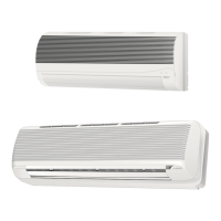
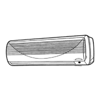
38BC / 38BH
R-410A
GB - 10
Electrical connections
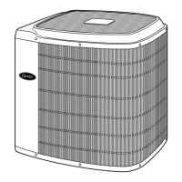
Notes: 1. Unit is suitable for outdoor installation.
2. Data referred to the outdoor unit only.
3. Starting current duration is usually lower than 1 sec.
4. Wire size shown applies to line length up to 15 m.
5. If the indoor unit is provided with an electric heater, consult indoor unit installation manual for correct sizing of the wires.
6. The indoor - outdoor unit interconnecting wires must be A07 RN-F type (245 IEC 57) or higher, with synthetic rubber insulation with Neoprene
coating, according to EN 60335-2-40 codes.
7. The mains supply connecting cable for 38BCS units must be H07 RN-F type (245 IEC 57) or higher, with synthetic rubber insulation with
Neoprene coating, according to EN 60335-2-40 codes.
The mains supply must be connected as follows:
Models 38BC and 38BH: to the indoor unit.
Models 38BCS: to the outdoor unit.
• Open control box panel (valve cover panel).
• Make electrical connections between units prior to proceeding
to mains supply unit connection.
• Connect the wires to the terminals according to the wiring
diagram and firmly tighten.
• Before proceeding with the unit connection to the mains supply
locate live L and neutral N, then make connections as shown
in the wiring diagram.
• Check that the impedance of the mains power supply is in
conformance with the unit power input indicated on the electric
data table IV.
• Ensure that mains supply connection is made through a switch
that disconnects all poles, with contact gap of a least 3 mm.
• The indoor - outdoor unit interconnecting wires must be A07 RN-F
type (245 IEC 57) or higher, with synthetic rubber insulation with
Neoprene coating, according to EN 60335-2-40 codes.
• The mains supply connecting cable for 38BCS units, must be
H07 RN-F type (245 IEC 57) or higher, with synthetic rubber
insulation with Neoprene coating, according to EN 60335-2-40
codes.
Notes:
1. Refer to the indoor unit installation manual for sizing of
the power supply wires.
2. All field electrical connections are the responsibility of the
installer.
3. After connections have been completed, replace control
box panel.
• Make refrigerant connections before electrical
connections.
When disconnecting, disconnect electrical connections before
refrigerant connections.
IMPORTANT:
Make ground connection prior to any other electrical
connections.
Table IV: Electrical data
Cooling only A A W A W A W A W A mm
2
mm
2
38BC 007 17 3.3 740 4.0 810 --- --- --- --- 10 1.5 1.5
38BC 009 24 4.0 890 5.2 1035 --- --- --- --- 12 1.5 1.5
38BC 012 28 5.4 1160 8.4 1625 --- --- --- --- 16 2.5 2.5
38BC 014 36.5 6.7 1480 9.4 1870 --- --- --- --- 20 2.5 2.5
38BCS 009 24 4.0 890 5.2 1035 --- --- --- --- 12 1.5 1.5
38BCS 012 28 5.4 1160 8.4 1625 --- --- --- --- 16 2.5 1.5
38BCS 014 36.5 6.7 1480 9.4 1870 --- --- --- --- 20 2.5 1.5
Heat pump A A W A W A W A W A mm
2
mm
2
38BH-007 17 3.4 730 4.8 920 2.9 650 4.7 920 10 1.5 1.5
38BH-009 24 3.7 810 4.7 920 3.8 820 5.9 1160 12 1.5 1.5
38BH-012 28 4.9 1080 7.1 1370 5.1 1110 8.3 1590 16 2.5 2.5
38BH-014 36.5 6.8 1470 9.4 1860 6.3 1420 9.3 1840 20 2.5 2.5
Indoor-
outdoor
unit
Starting
current
(3)
Heating
Cooling
Power input
(2)
Main power
connections
(7)
Time-delay
fuse
gL type
Wire size
(4-5)
Nominal conditions
230V
~
50Hz
ISO 5151.2/T1
indoor 27°C d.b. 19°C w.b.
outdoor 35°C d.b. 24°C w.b.
Peak conditions
198V
~
50Hz
ISO 5151.2/T1
indoor 32°C d.b. 23°C w.b.
outdoor 43°C d.b. 32°C w.b.
Nominal conditions
230V
~
50Hz
ISO 5151.2/High+
indoor 20°C d.b. 15°C w.b.
outdoor 7°C d.b. 6°C w.b.
Peak conditions
198V
~
50Hz
ISO 5151.2/High+
indoor 27°C
outdoor 24°C d.b. 18°C w.b.
Wire size
(4-5-6)