6
SYSTEM REQUIREMENTS
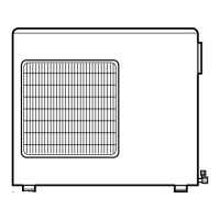
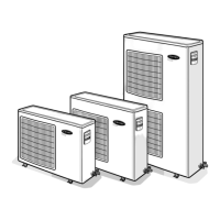
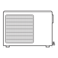
Allow sufficient space for airflow and unit servicing. See Fig. 22 through 26 for the minimum required clearances.
Piping
IMPORTANT: Both refrigerant lines must be insulated separately.
The minimum refrigerant line length between the indoor and outdoor units is 10 ft. (3m). See Table 11 for the maximum lengths.
Table 11—Maximum Piping Lengths
Outdoor Unit
System Size 18 24 30 36 42 48 56
Piping
Min. Piping Length ft 10 10 10 10 10 10 10
Standard Piping Length ft 32 98 131.2 131.2 131.2 98.42 98.42
Max. outdoor-indoor height difference ft 33 33 49.2 49.2 49.2 98.42 98.42
Max. height distance between indoor and indoor ft 33 33 24.6 24.6 24.6 49.21 49.21
Max. height distance between indoor and outdoor and indoor ft 32 32 49.2 49.2 49.2 98.42 98.42
Max. height distance between indoor and outdoor and outdoor up ft 33 33 49.2 49.2 49.2 98.42 98.42
Max. equivalent piping outdoor to last indoor ft 33 65 82 82 82 229 229
Max. Piping Length with no additional refrigerant charge ft 32 98 131.2 131.2 131.2 98.42 98.42
Max. Piping Length ft 65 196 229.7 246 246 442.9 475.7
Gas Pipe (size - connection type) in 3/8 3/8 3/8 3/8 3/8 5/8 5/8
Liquid Pipe (size - connection type) in 1/4 1/4 1/4 1/4 1/4 3/8 3/8
Refrigerant
Refrigerant Type R-410A R-410A R-410A R-410A R-410A R-410A R-410A
Heat Pump Models Charge Amount Lbs 3.53 4.85 6.17 8.05 8.05 10.91 10.91
NOTE: Tables 12 through 16 display the piping size specifications.
Table 12—Indoor Unit Piping Connection High Wall
Indoor High Wall
(40GRQ)
SIZE 9 12 18
Pipe Connection Size - Liquid in 1/4" 1/4" 1/4"
Pipe Connection Size - Suction in 1/2" 1/2" 5/8"
Table 13—Indoor Piping Connection High Wall
Indoor High Wall
(40GJB)
SIZE 9 12 18 24
Pipe Connection Size - Liquid in 1/4" 1/4" 1/4" 1/4"
Pipe Connection Size - Suction in 1/2" 1/2" 5/8" 5/8"
Table 14—Indoor Piping Connection Cassette
Indoor Cassette
SIZE 12 18 24
Pipe Connection Size - Liquid in 1/4" 1/4" 3/8"
Pipe Connection Size - Suction in 3/8" 1/2" 5/8"
Table 15—Indoor Piping Connection Ducted
Indoor Ducted
SIZE 9 12 18 21 24
Pipe Connection Size - Liquid in 1/4" 1/4" 1/4" 3/8" 3/8"
Pipe Connection Size - Suction in 3/8" 3/8" 1/2" 5/8" 5/8"
Table 16—Indoor Piping Connection Floor Console
Indoor Floor Console
SIZE 9 12 18
Pipe Connection Size - Liquid in 1/4" 1/4" 1/4"
Pipe Connection Size - Suction in 3/8" 3/8" 1/2"
Table 17—Additional Refrigerant Charge
TOTAL LINE
LENGTH ft.
ADDITIONAL CHARGE, 1/4” LIQUID LINE / 3/8” LIQUID LINE, oz/ft. ft. (m)
Unit
Size
Min Max
10-32
(3-10)
>32-66
(10-20)
>66-98
(20-30)
>98-131.2
(30-40)
>131.2-196
(40-60)
>196-230
(60-70)
>230-246
(70-75)
>246-443
(75-135)
>443-476
(135-145)
18 10 66
None
0.20 / 0.20
24 10 196 None None 0.20 / 0.20 0.20 / 0.20
30 10 230 None None None 0.24 / 0.58 0.24 / 0.58
36 10 246 None None None 0.24 / 0.58 0.24 / 0.58 0.24 / 0.58
42 10 246 None None None 0.24 / 0.58 0.24 / 0.58 0.24 / 0.58
48 10 443 None None 0.24 / 0.58 0.24 / 0.58 0.24 / 0.58 0.24 / 0.58 0.24 / 0.58
56 10 476 None None 0.24 / 0.58 0.24 / 0.58 0.24 / 0.58 0.24 / 0.58 0.24 / 0.58 0.24 / 0.58
Additional Refrigerant Calculation Sizes 30K, 36K and 42K:
Sum Total Liquid Pipe 1/4” (ft.) x 0.24 + Sum Total Liquid Pipe 3/8” (ft.) x 0.58 – 31 oz
Additional Refrigerant Calculation Sizes 48K and 56K:
Sum Total Liquid Pipe 1/4” (ft.) x 0.24 + Sum Total Liquid Pipe 3/8” (ft.) x 0.58 – 51.7 oz
NOTE: If the calculation results in a negative number no additional refrigerant is required.
NOTES:
EXV = Electronic Expansion Device
Electronic expansion valves in the outdoor unit are used as metering devices.
 Loading...