4
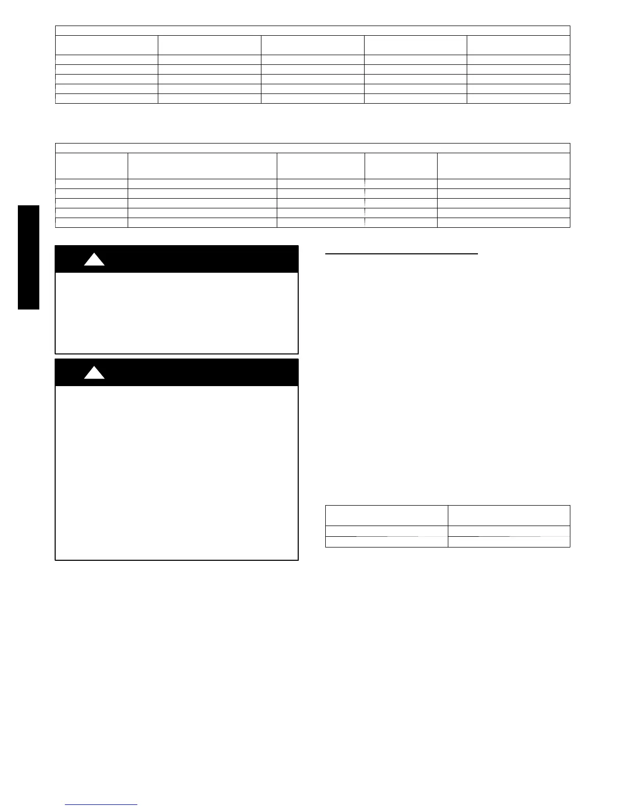
Refrigerant Charge
Unit Size
Charge
oz. (kg.)
Additional Charge
Required After ft. (m)
Additional Charge
oz./ft. (g/m)
Metering Device
18 K 47.6 (1.35) 20 (6.1) 0.21 (20) EXV
24 K 77.6 (2.2) 30 (9.1) 0.21 (20) EXV
30 K 77.6 (2.2) 40 (12.2) 0.21 (20) EXV
36 K 102.2 (2.9) 40 (12.2) 0.235 (22) EXV
42 K 169.3 (4.8) 150 (45.7) 0.235 (22) EXV
NOTES:
EXV = Electronic Expansion Device
Electronic expansion valves in the outdoor unit are used as metering devices.
Electrical Data
Unit Size
System Voltage
V o l t s --- P h --- F r e q
Operating Voltage
(Min/Max)
MCA
Max
Fuse/CB Amps
(MOCP)
18K 208/230 ---1 ---60 187/253 13 20
24K 208/230 ---1 ---60 187/253 20 30
30K 208/230 ---1 ---60 187/253 26 45
36K 208/230 ---1 ---60 187/253 28 45
42K 208/230 ---1 ---60 187/253 29 50
CAUTION
!
EQUIPMENT DAMAGE HAZARD
Failure to follow this caution may result in equipment
damage or improper operation.
S Wires should be sized based on NEC and local codes.
S Use copper conductors only with a minimum 300 volt .
rating and 2/64 inch thick insulation.
CAUTION
!
EQUIPMENT DAMAGE HAZARD
Failure to follow this caution may result in equipment damage
or improper operation.
S Be sure to comply with local codes while running wire from
indoor unit to outdoor unit.
S Every wire must be connected firmly. Loose wiring may
cause terminal to overheat or result in unit malfunction. A
fire hazard may also exist. Therefore, be sure all wiring is
tightly connected.
S No wire should be allowed to touch refrigerant tubing,
compressor or any moving parts.
S Disconnecting means must be provided and shall be located
within sight and readily accessible from the air conditioner.
S Connecting cable with conduit shall be routed through hole
in the conduit panel.
Connecting (Power and Control
Cable)
Power Wiring:
The main power is supplied to the outdoor unit. The field supplied
connecting cable from the outdoor unit to indoor unit consists of
three (3) wires and provides the power for the indoor unit. Two
wires are high voltage AC power and one is a ground wire.
Consult your local building codes and the NEC (National
Electrical Code) or CEC (Canadian Electrical Code) for special
requirements.
All wires must be sized per NEC or CEC and local codes. Use
Electrical Data table MCA (minimum circuit amps) and MOCP
(maximum over current protection) to correctly size the wires and
the disconnect fuse or breakers respectively.
Per caution note, only copper conductors with a minimum 300 volt
rating and 2/64--inch thick insulation must be used.
Control Wiring:
A separate shielded copper conductor only, with a minimum 300
volt rating and 2/64--inch thick insulation, must be used as the
communication wire from from the outdoor unit to the indoor unit.
To minimize voltage drop of the control wire, use the following
wire size and maximum lengths shown in the chart below.
Wire Size
Length
ft (m)
18 AWG 50 ft. (15 m)
16 AWG 50 ft (15) to 100 ft. (30 m)
38/40GVM

 Loading...