3
SAFETY CONSIDERATIONS
Installing, starting up, and servicing air--conditioning equipment
can be hazardous due to system pressures, electrical components,
and equipment location (roofs, elevated structures, etc.).
Only trained, qualified installers and service mechanics should
install, start--up, and service this equipment.
Untrained personnel can perform basic maintenance functions such
as cleaning coils. All other operations should be performed by
trained service personnel.
When working on the equipment, observe precautions in the
literature and on tags, stickers, and labels attached to the
equipment.
Follow all safety codes. Wear safety glasses and work gloves. Keep
quenching cloth and fire extinguisher nearby when brazing. Use
care in handling, rigging, and setting bulky equipment.
Read these instructions thoroughly and follow all warnings or
cautions included in literature and attached to the unit. Consult
local building codes and current editions of the National Electrical
Code ( NEC ) NFPA 70. In Canada, refer to current editions of the
Canadian electrical code CSA 22.1.
Recognize safety information. This is the safety--alert symbol
!
!
.
When you see this symbol on the unit and in instructions or
manuals, be alert to the potential for personal injury.Understand
these signal words: DANGER, WARNING, and CAUTION.
These words are used with the safety--alert symbol. DANGER
identifies the most serious hazards which will result in severe
personal injury or death. WARNING signifies hazards which
could result in personal injury or death. CAUTION is used to
identify unsafe practices which may result in minor personal injury
or product and property damage. NOTE is used to highlight
suggestions which will result in enhanced installation, reliability, or
operation.
!
WARNING
ELECTRICAL SHOCK HAZARD
Failure to follow this warning could result in personal
injury or death.
Before installing, modifying, or servicing system, main
electrical disconnect switch must be in the OFF
position. There may be more than 1 disconnect switch.
Lock out and tag switch with a suitable warning label.
CAUTION
!
EQUIPMENT DAMAGE HAZARD
Failure to follow this caution may result in equipment
damage or improper operation.
Do not bury more than 36 in. (914 mm) of refrigerant pipe
in the ground. If any section of pipe is buried, there must be
a 6 in. (152 mm) vertical rise to the valve connections on
the outdoor units. If more than the recommended length is
buried, refrigerant may migrate to the cooler buried section
during extended periods of system shutdown. This causes
refrigerant slugging and could possibly damage the
compressor at start--up.
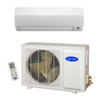
GENERAL
These instructions cover the installation, start--up and servicing of
the 38GVM outdoor unit connected to up to four 40GVM indoor
high wall units. For approved combinations, please refer to the
Product Data.
SYSTEM REQUIREMENTS
Allow sufficient space for airflow and servicing unit. See Fig. 7
through 9 for minimum required clearances.
Piping
IMPORTANT: Both refrigerant lines must be insulated
separately.
Minimum refrigerant line length between the indoor and outdoor
units is 10 ft. (3 m).
The following maximum lengths are allowed:
Refrigerant Line lengths ft (m)
Unit Size 18 K 24 K 30 K 36 K 42 K
Total Piping
66
(20)
230
(70)
230
(70)
230
(70)
262
(80)
Max Pipe Length to
Any One FCU
33
(10)
66 (20)
82
(25)
Max Elevation (ID to
ID)
16.4
(5)
33 (10) 25 (7.5)
Max Elevation (ID
over OD)
16.4
(5)
33 (10) 50 (15)
Max Elevation (OD
over ID)
16.4
(5)
33 (10) 50 (15)
The following are the piping sizes:
Outdoor Unit Service Valve Sizes
Unit Size Number of Valves Mix Phase Vapor
18K 2 1/4” 3/8”
24K 3 1/4” 3/8”
30K 4 1/4” 3/8”
36K
2 1/4” 3/8”
1 1/4” 1/2”
1 3/8” 5/8”
42K
2 1/4” 3/8”
2 1/4” 1/2”
1 3/8” 5/8”
Indoor Unit Piping Co nnection Sizes
Unit Size Mix Phase Vapor
9 & 12K 1/4” 3/8”
18 K 1/4” 1/2”
Refrigerant Piping:
Line sets to be sized based on the connection size of the indoor
unit. Each pipe to be insulated individually.
Conversion Joints:
The 38GVM may include a package of conversion joints to
facilitate installation of various sizes of fan coils. These joints are to
be connected to the outdoor unit as needed to match the line set
size.
38/40GVM

 Loading...