SAFETY CONSIDERATIONS
Installing, starting up, and servicing air-conditioning equipment
can be hazardous due to system pressures, electrical components,
and equipment location (roofs, elevated structures, etc.).
Only trained, qualified installers and service mechanics should
install, start-up, and service this equipment.
Untrained personnel can perform basic maintenance flmctions such
as cleaning coils. All other operations should be performed by
trained service personnel.
When working on the equipment, observe precautions in the
literature and on tags, stickers, and labels attached to the
equipment.
Follow all safety codes. Wear safety glasses and work gloves. Keep
quenching cloth and fire extinguisher nearby when brazing. Use
care in handling, rigging, and setting bulky equipment.
Read these instructions thoroughly and follow all warnings or
cautions included in literature and attached to the unit. Consult
local building codes and current editions of the National Electrical
Code ( NEC ) NFPA 70. In Canada, refer to current editions of the
Canadian electrical code CSA 22.1.
Recognize safety information. This is the safety-alert symbol/}k .
When you see this symbol on the unit and in instructions or
manuals, be alert to the potential for personal injury.Understand
these signal words: DANGER, WARNING, and CAUTION.
These words are used with the safety-alert symbol. DANGER
identifies the most serious hazards which will result in severe
personal injury or death. WARNING signifies hazards which
could result in personal injury or death. CAUTION is used to
identify unsafe practices which may result in nfinor personal injury
or product and property damage. NOTE is used to highlight
suggestions which will result in enhanced installation, reliability, or
operation.
ELECTRICALSHOCK HAZARD
Failure to follow this warning could result in personal
injury or death.
Before installing, modifying, or servicing system, main
electrical disconnect switch must be in the OFF
position. There may be more than 1 disconnect switch.
Lock out and tag switch with a suitable warning label.
EQUIPMENT DAMAGE HAZARD
Failure to follow this caution may result in equipment
damage or improper operation.
Do not bury more than 36 in. (914 ram) of refrigerant pipe
in the ground. If any section of pipe is buried, there must be
a 6 in. (152 ram) vertical rise to the valve connections on
the outdoor units. If more than the recommended length is
buried, refrigerant may nfigrate to the cooler buried section
during extended periods of system shutdown. This causes
refrigerant slugging and could possibly damage the
compressor at start-up.
GENERAL
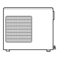
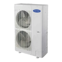
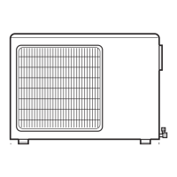
These instructions cover the installation, start-up and servicing of
the 38GXM outdoor unit connected to up to four 40GXM indoor
high wall units. For approved combinations, please refer to the
Product Data.
SYSTEM REQUIREMENTS
Allow sufficient space for airflow and servicing unit. See Fig. 2
and 3 for minimum required clearances.
IMPORTANT: Both refrigerant lines must be insulated
separately.
• Minimum refrigerant line length between the indoor and outdoor
units is 10 ft. (3 m).
The following maximum lengths are allowed:
REFRIGERANT LINE LENGTHSR (m)
Unit Size 18 K 24 K 30 K
Total Piping 124 (38) 124 (38) 230 (70)
Max Pipe Length to Any One 82 (25) 82 (25) 82 (25)
FCU
Max Elevation (ID overOD) 49 (15)
Max Elevation (OD over ID) 33 (10)
The following are the piping sizes.
UNIT SERVICE VALVESIZE*
Unit Size Mix Phase Vapor
18 & 30 K 1/4" 3/8"
24 K 1/4" 1/2"
Unit can have 2 or 4 service valveswith the same pipe sizes
CONVERSION JOINTS
Model Qty.and When Used
Type
lx
38GXM218---3 (3/8 to 1/2) Connecting Size 12 K FCU
2x
38GXM224---3 (1/2 to 3/8) Connecting Size 9 K FCU
3x Connecting Size 12
38GXM430---3
(3/8 to 1/2) or 18 K FCU
Refrigerant Charge
REFRIGERANTCHARGE
ChargeWeight lb. (kg)
3.5 (1.6)
5.5 (2.5)
7.3 (3.3)
Unit Size
18K
24 K
30 K
Above charge is for piping runs up to 50 ft. (15 m) per system
for sizes 18 and 24 and 100 fl (30 m) per system for size 30.
• For piping runs greater than those listed above, add 0.23 oz
for size 18, 0.17 oz for size 24, and 0.54 oz for size 30 of
refrigerant per foot of extra piping up to the allowable
length.
• Electronic expansion valves in the outdoor unit are used as
metering devices.
Connecting (Power and Control Cable)
• The main power is supplied to the outdoor unit. The field
supplied connecting cable from the outdoor unit to indoor unit
consists of four wires and provides the power for the indoor unit
as well as the communication signal and ground between the
outdoor and indoor unit.
Two wires are high voltage AC power, one is high voltage
controls and one is a ground wire.
• Consult local building codes, NEC (National Electrical Code) or
CEC (Canadian Electrical Code) for special requirements.
MIN. CKT AMP
UNIT SIZE POWER SOURCE MAX FUSE/CB
AMP
18k 208/230-1-60 14/20
24k 208/230-1-60 20/30
30k 208/230-1-60 24/40
Connecting Cable: Voltage drop on the connecting cable
should be kept to a minimum. Do not use thermostat wire,
Use minimum 14AWG 4 conductor cable (solid or stranded).
 Loading...