3
(FIELD PROVIDED AND INSTALLED)
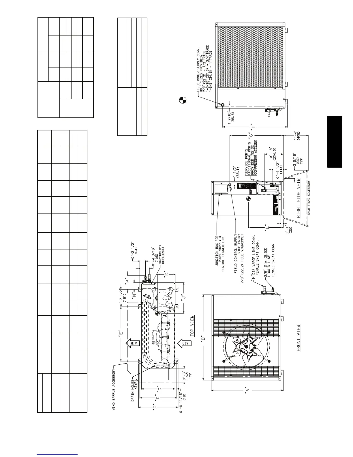
NOTE: Dimensions shown in feet--inches. Dimensions in ( ) are millimeters.
UNIT MODELS
CHASSIS
SIZE
(Reference)
ABC D E FG H JKL NP
38HDR
Unit Size
018
0
2’--1
1
/
8”
3’-- 0
15
/
16”
1’-- 2
9
/
16”
1’-- 4” 1’--11
7
/
16”
1’-- 5
3
/
16”
1’--5
1
/
8”
1’--10” 1’-- 1” 0’--6
5
/
8”
0’--11
1
/
4”
0’-- 2
15
/
16”
0’-- 6”
(638.2) (938.2) (369.9) (406.4) (595.3) (436.6) (435) (559.1) (330.2) (168.3) (285.8) (75) (152.4)
024
0.6
2’--7
1
/
8”
3’-- 0
15
/
16”
1’-- 2
9
/
16”
1’-- 4” 1’--11
7
/
16”
1’-- 5
3
/
16”
1’--11
1
/
8”
2 ’ -- 4 ” 1 ’ -- 2 ” 0 ’ -- 6
3
/
4”
0’--11
5
/
8”
0’-- 2
15
/
16”
0’-- 6”
(790.6) (938.2) (369.9) (406.4) (595.3) (436.6) (587.4) (711.5) (355.6) (171.5) (295.3) (75) (152.4)
030, 036
1.0
3’-- 1
3
/
16”
1’-- 5
1
/
16”
1’-- 6
7
/
16”
2’--6
1
/
2”
1’--7
5
/
8”
2’-- 5
3
/
16”
2’--10
1
/
16”
1’-- 1
11
/
16”
0’--8
1
/
8”
1’--3
7
/
8”
0’--3
7
/
16”
0’--6
1
/
2”
(944.6) (1131.9) (433.4) (468.3) (774.7) (498.5) (741) (865.5) (347.7) (206.4) (403.2) (88) (165.4)
048, 060
1.6
3’-- 7
3
/
16”
1’-- 5
1
/
16”
1’-- 6
7
/
16”
2’--6
1
/
2”
1’--7
5
/
8”
2’-- 11 /
13/16”
3’-- 4
1
/
16”
1’--2
1
/
2”
0’--8
1
/
2”
1’--6
7
/
8”
0’-- 3
7
/
16”
0’--6
1
/
2”
(1097) (1131.9) (433.4) (468.3) (774.7) (498.5) (893.4) (1017.9) (354.2) (215.9) (479.4) (88) (165.4)
UNIT SIZE M
OPER ATIN G WT
in. mm lb kg
38HDR
018
5
/
8
15.88 166 75.8
024
5
/
8
15.88 176 79.8
030
3
/
4
19.05 187 84.8
036
3
/
4
19.05 250 113.4
048
7
/
8
22.22 278 126.1
060
7
/
8
22.22 306 138.8
NOTES:
1. Required clearances: with coil facing wall, allow 6 in. minimum clearance
on coil side and coil end, and 3 feet minimum clearance on compressor
end and fan side. With fan facing wall, allow 8 in. minimum clearance on
fan side and coil end, and 3 feet minimum clearance on compressor end
and coil side. With multi--unit application, arrange units so discharge of one
does not enter inlet of another.
2. Dimensions in parenthesis are in millimeters.
3. Center of Gravity .
UNIT SIZE
MINIMUM MOUNTING PAD
DIMENSIONS
Support Feet
ft--in. mm
CHASSIS SIZES 0 & .6 1 -- 11 x3 --6 584.2 x 1066.8
CHASSIS SIZES 1 & 1.6
2--0x4--2
609.6 x 1270
3’ -- 8
9/16”
3’ -- 8
9/16”
Fig. 2 --- 38 HDR Unit Dimensions
38HDR
 Loading...