Do you have a question about the Carrier 38HD018 and is the answer not in the manual?
Observe literature, tags, labels, codes. Wear safety gear, have fire extinguisher. Read instructions thoroughly.
Turn off main power before installation/servicing. Turn off accessory heater power if applicable. Electrical shock can cause personal injury.
Unpack unit, inspect shipment, and consider system requirements. Ensure adequate space for airflow, wiring, and piping.
Verify the correct Accurater (bypass type) refrigerant control for cooling system capacity optimization.
Mount on a solid, level concrete pad or a level platform/frame. Consider roof mounting as an option.
Ensure unit panels are secure. Use appropriate slings and spreader bars to prevent damage during lifting.
The filter drier is factory supplied. A moisture indicator (sight glass) is a field-supplied option.
A fusible plug is in the suction line. Do not cap it. Install additional safety devices as required by local code.
Unit is factory wired for nameplate voltage. Provide adequate fused disconnect switch. Use minimum 60°C wire for field power connection.
Control voltage is 24 volts (40 va minimum). Route control wires through unit side panel to the control box.
To avoid personal injury, ensure indoor blower has stopped before attempting service or maintenance.
Verify internal wiring, power source, and open service valves. Ensure crankcase heater is tight.
Field piping must be leak tested and evacuated to 1000 microns to eliminate contamination and moisture.
Energize crankcase heater by setting thermostat above ambient to prevent refrigerant migration and oil dilution.
Backseat service valves to close the service port. Failure can result in system charge loss or personal injury.
Release holding charge by opening service valves. Add charge as required. Refer to Table 1 for indoor sections.
After crankcase heater runs 24 hrs, set thermostat below ambient. Unit starts after a 5-minute delay.
Turn off main power before maintenance. Failure can cause shock or injury from rotating fan blade.
Check fan mounting, relief valve, overload. Use pumpdown for low-side repairs. Replace filter drier when moisture is indicated.
Use Tables 4 and 5 to check and adjust charge during cooling season. Operate unit 15 minutes before checking.
Install Time Guard II device in the 24-v control circuit to protect the compressor from short cycling.
Turn off unit power before maintenance. Failure can cause shock or injury from rotating fan blade.
Compressor has factory oil. Replace oil when lost. Refer to Service Techniques Manual for recharging procedure.
Lubricate fan motor bearings annually or every 3-5 years based on environment and operating time. Use SAE-10 oil.
Clean coils annually or as required using water or compressed air. Flush dirt and debris from drain holes.
This chart helps diagnose and resolve cooling cycle issues such as no cooling, insufficient cooling, high suction, low head pressure, etc.
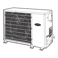
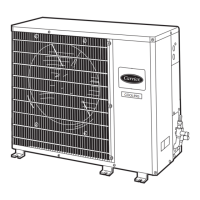
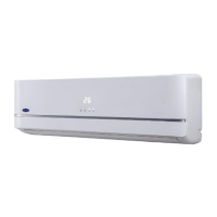
The 38HD Split System Condensing Units are designed for air conditioning applications, offering a range of models suitable for various residential and light commercial settings. These units are integral components of a split system, working in conjunction with an indoor evaporator coil to provide cooling.
The primary function of the 38HD condensing unit is to reject heat from the refrigerant cycle to the outdoor air, thereby cooling the indoor space. It houses the compressor, condenser coil, and condenser fan motor, which are essential for the refrigeration process. The compressor circulates refrigerant, increasing its pressure and temperature. The hot, high-pressure refrigerant then flows through the condenser coil, where the condenser fan draws outdoor air across the coil, facilitating heat transfer and causing the refrigerant to condense into a liquid. This liquid refrigerant then travels to the indoor evaporator coil, where it absorbs heat from the indoor air, completing the cooling cycle.
The unit incorporates an Accurater® (bypass type) refrigerant control, which is crucial for optimizing cooling system capacity. This control, typically located on the evaporator, uses a field-replaceable piston to regulate refrigerant flow. The correct piston size is determined by the specific condenser/evaporator system being installed, ensuring efficient operation.
Safety is a key aspect of the 38HD design. The unit includes a high-pressure switch on the discharge line to protect against excessive discharge pressures caused by issues like overcharge, condenser fan motor failure, or system restrictions. It also features a low-pressure switch on the suction line with fixed, non-adjustable settings, which ensures the compressor shuts down if suction pressure drops below a safe threshold. A fusible plug is located in the suction line as a safety relief device.
For enhanced compressor protection, a crankcase heater is integrated into the unit. This heater prevents refrigerant migration and compressor oil dilution during shutdown periods, especially when the compressor is not operating for extended durations. This is vital for preventing compressor damage during start-up. Additionally, an internal current and temperature sensitive overload protects the compressor motor by automatically resetting when the motor temperature returns to a safe level.
The 38HD units are designed for ground or roof mounting, offering flexibility in installation. They feature horizontal air discharge, which helps in efficient heat dissipation.
Installation of the 38HD unit requires careful attention to several factors to ensure optimal performance and safety. The unit should be mounted on a solid, level concrete pad or platform, positioned to avoid water or ice dripping directly onto it. Adequate space for airflow clearance, wiring, refrigerant piping, and servicing must be maintained around the unit. The condenser airflow should be unrestricted on both sides.
Refrigerant piping connections are critical. Field-supplied tubing of refrigerant grade, correct size, and condition must be used. It is recommended to use at least 10 ft of interconnecting tubing and to avoid burying more than 3 ft of the line set underground to prevent refrigerant migration and potential compressor damage. If refrigerant tubing or the indoor coil is exposed to atmospheric conditions for more than 5 minutes, it must be evacuated to 1000 microns to eliminate contamination and moisture. A filter drier is factory-supplied, and a moisture indicator (sight glass) is a field-supplied option that should be installed just after the liquid line shutoff valve. When brazing refrigerant lines, nitrogen or another inert gas should be passed through the piping to prevent copper oxide formation, and service valves should be wrapped with a heat-sinking material to prevent damage.
Electrical connections must comply with the National Electrical Code (NEC) and local codes. A fused disconnect switch, readily accessible but out of reach of children, must be provided within sight of the unit. The unit is factory wired for the voltage shown on the nameplate, and only copper wire with a minimum 60 C rating should be used for field power connections. For 3-phase units, voltages between phases must be balanced within 2% to prevent abuse and potential damage to electrical components.
Charging the system involves releasing the factory holding charge into the system by opening the liquid and suction line service valves. Additional refrigerant is added as required, based on the total system charge specified in the manual. The unit should be operated for a minimum of 15 minutes before checking and adjusting the refrigerant charge using the provided superheat and suction-tube temperature tables.
The Time Guard® II device, an optional accessory, can be installed to protect the compressor from short cycling. This device provides a 5-minute delay before restarting the compressor after shutdown, which is beneficial for compressor longevity.
Regular maintenance is essential for the longevity and efficient operation of the 38HD condensing unit. Before performing any maintenance, the main power switch to the unit must be turned off to prevent electric shock or injury from the rotating fan blade.
Lubrication of the compressor is not typically a routine maintenance item as it comes with a factory oil charge. However, if oil is lost, it must be replaced with the specified type and quantity. The fan motor bearings require periodic lubrication. Oiling holes are provided at each end of the condenser fan motor. The frequency of lubrication depends on environmental conditions and operating time: annually for very dirty environments with high ambient temperatures and long operating hours, every 3 years for reasonably clean environments with moderate temperatures and operating hours, and every 5 years for clean environments with low operating hours.
Cleaning the condenser coils is a crucial maintenance task. The blow-through design of the coils can lead to dirt and debris accumulation, which restricts condenser airflow. Coils should be cleaned annually or as needed, depending on the location and outdoor air conditions. This involves turning off unit power and flushing the coil from the outside with a water hose or other suitable equipment, ensuring all dirt and debris are removed from the drain holes in the unit's base.
Troubleshooting guidance is provided for common issues such as "No Cooling or Insufficient Cooling" and "Compressor Will Not Run," with a detailed chart to help diagnose problems. This includes checking for dirty air filters, restricted ducts, faulty electrical components, low refrigerant charge, and compressor issues.
The service valves are designed to isolate the refrigerant charge from the line set connection ports. For servicing, the valves must be fully backseated to close the service port, as there is no Schrader valve at the service port, and failure to backseat the valve could result in loss of system charge or personal injury. The piston in the Accurater® refrigerant control can be checked, cleaned, or replaced by following a specific procedure that involves pumping down the unit and carefully removing the retainer and piston.
| Model | 38HD018 |
|---|---|
| Cooling Capacity | 18, 000 BTU/h |
| Refrigerant | R-410A |
| Phase | 1 |
| Voltage | 208-230V |