Step 2 -- Mount Unit
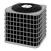
MOUNTING OUTDOOR UNIT ON GROUND
(Fig. 4) -- Mount unit on a solid, level concrete pad. Position
unit so water or ice from roof does not fall directly onto unit. If
conditions or local codes require unit be fastened to a pad,
4 field-supphed tiedown bolts should be used and fastened
through slots provided in unit mounting feet.
If the unit will be located in areas where heavy snowfall
may occur, raise the level of the unit to 8 in. above the usual
snow level.
MOUNTING OUTDOOR UNIT ON ROOF -- Mount unit
on a level platform or frame at least 6 in. above roof surface.
Isolate unit and tufting from structure. Refer to Fig. 5.
ff the unit will be located in areas where heavy snowfall
may occur, raise the level of the unit to 8 in. above the usual
snow level or use an outdoor unit bracket kit.
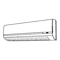
MOUNTING INDOOR UNIT ON WALL (Fig. 6-8) -- Be-
fore mounting the indoor unit on the wall with a wall hanging
bracket, consider how the indoor unit will be connected to the
refrigerant pilPmg. The indoor unit can be connected in four
ways. Refer to Fig. 6 for connection opuons. When the piping
is connected to points 1, 2 or 4, remove the knock-out either at
the side or at the bottom of the unit.
The indoor units are mounted on the wall with a wall hang-
ing bracket. Position the wall hanging bracket so that it is flush
with the wall. See Fig. 8 and 9 for service clearances.
I I
i, 18.5In. ,j
i i
i i
i i
\
No. 4 Pins
1/4 in.
Fig. 4 -- Mounting Outdoor Unit On A Pad
@
Fig. 6 -- Indoor Unit Piping Configurations
Sin. rain.
18in.
12 in. . . rain.
Plumb line
• o . . . • , •
screw
Fig. 7 -- Installing the Wall Bracket
O
e
_) 6in. rain.
_) Gradient.
_) Gravel-filled trench.
Fig. 5 -- Mounting Outdoor Unit on Roof
A/
2_in. 1 1/2 in
9 1/2 in.
95 in.
18 in. 4 I/2 in.
\B I
4 1/2 in.
Fig. 8 -- Wall Bracket Dimensions
6
 Loading...