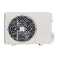
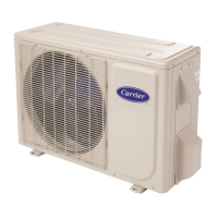
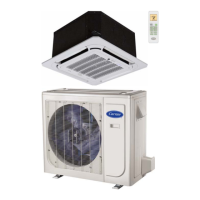
pump model.
CODE PART NAME
L_IN FireWire L input terminal
CN11 Zero line N input terminal
CN16 Internal and external communication line interface
CN6 Indoor fan interface
CN4 Fan feedback interface
CN5 Stepper motor interface
P_1 Ground interface
CN8 Room temperature sensor interface
CN9 Pipe temperature sensor interface
CN10A Display interface
CN1 Electronic expansion valve interface
CN14 Compressor top temperature sensor (optional)
CN15 Exhaust temperature sensor
CN16 Outdoor temperature & amp; condenser pipe temperature sensor
CN10 DC fan output port (no)
CN19 AC fan output port
CN33 Electric heating wire line N
CN34 Electric heating wire line L
CN26,CN28 Four way valve control port
CN4 Power L input terminal
CN5 Power N input terminal
CN6 Ground wire
CN7 Communication line
CN8,CN9 Reactor connected line port
CN36,CN37 PFC capacitor connected line port
N-B Power L input terminal
CN17 Test panel interface
U V W Compressor connection port
Fig. 6 – Wiring Diagram 38/40MFC/MFQ009 / 38/40MFC/MFQ012 (115V)

 Loading...


