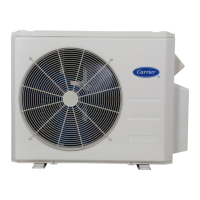
38MGRBQ: Service Manual
Manufacturer reserves the right to change, at any time, specifications and designs without notice and without obligations.
88
4 COMPRESSOR HOW TO REMOVE THE COMPRESSOR REMARKS
1. Perform the steps from sections 1, 2 and 3.
2. Remove the electrical control box and partition plate.
3. Extract the refrigerant gas.
4. Remove the sound insulation material and crankcase
heating cable.
5. Remove the compressor’s terminal cover and disconnect
the wires of the compressor thermo and the compressor
from the terminal.
6. Remove the discharge pipe.and suction pipe with a burner.
7. Remove the hex nuts and washers securing the compressor
to the bottom plate.
8. Lift the compressor.
5 4-WAY VALVE REMOVE THE 4-WAY VALVE REMARKS
1. Perform the steps from sections 1 and 2.
2. Extract the refrigerant gas.
3. Perform the steps (remove the electrical parts) from
section 3.
4. Remove the coil screw and remove the coil.
5. Detach the welded parts of 4-way valve and pipe.
6 EXPANSION VALVE REMOVE THE EXMPANSION VALVE REMARKS
1. Perform the steps from sections 1 and 2.
2. Perform the steps (remove the electrical parts) from
section 3.
3. Remove the coils.
4. Detach the welded parts of the expansion valves and pipes.

 Loading...