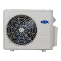
38MGRBQ: Service Manual
Manufacturer reserves the right to change, at any time, specifications and designs without notice and without obligations.
87
3 ELECTRICAL PARTS REMOVE ELECTRICAL PARTS REMARKS
1. Perform the steps from section 1.
2. Remove the 5 screws from the electrical control box cover.
Remove the cover.
3. Cut the ribbon and disconnect the 4-way valve connector
CN38 (2p,blue).
4. Turn over the main board.
5. Remove the electronic installing box subassembly (4
hooks).
6. Remove the electronic control box support.
7. Disconnect the connectors and wires connected to the PCB
and other parts.
8. Disconnect the grounding wire (yellow-green) after
removing the handle and the right-rear panel.
9. Remove the PCB board.
ĸ
Ĺ

 Loading...