29
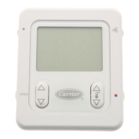
NOTE 1: This control is compatible with any kind of
electromechanical or electronic control (without anticipation
resistors) with the following features:
- Voltage at 24 V AC
50VZ units standard connections:
R Connection to 24 V
L Protection device indication
C Common 24 V
G Ventilation
Y1 First stage cooling
Y2 Second stage cooling
W1 First stage heating (option)
W2 Second stage heating (option)
50PZ units standard connections:
R Connection to 24 V
L Protection device indication
C Common 24 V
G Ventilation
Y1 First stage (cooling/heating)
Y2 Second stage (cooling/heating)
W1 First stage heating (option)
O Reversing valve*
* The O connection is activated in cooling.
NOTE 2: If the thermostat wiring is incorrect, the control will
be blocked (red LED on) and all the outlets will be deactivated
when unit power is supplied.
NOTE 3: The thermostat cables should be separate from any
220 V or 380 V cable.
Refrigerant line connections (38VZ/PZ and 40PZ)
To guarantee correct unit performance ensure that the line
length and number of bends are kept to a minimum. Avoid pipe
kinking by using large radius bends.
IMPORTANT: Always use refrigerant-grade deoxidized and
dehydrated copper tubing between the indoor and outdoor
units.
Before connecting the refrigerant lines carefully follow the
steps below:
- Remove the nitrogen holding charge from the refrigerant
circuits.
- Select the diameter of the copper tubing according the the
units installed and according to the distance between the
indoor and outdoor units.
- Use silver alloy rod for soldering purposes, and ensure
that this work is done in a nitrogen atmosphere.
- To avoid oxidation insulate the refrigerant lines
adequately.
- Pull a vacuum in the refrigerant circuit until a pressure of
6.9 Pa is maintained for at least 2 hours.
- Charge the refrigerant circuit with the necessary amount
of R-407C refrigerant (in accordance with table 1 and the
length of the refrigerant lines).
- Check there are no refrigerant leaks.
Refrigerant line selection
General
When designing refrigerant lines the following must be kept in
mind:
- Depending on the unit arrangement:
Fig. 22 - Refrigerant lines option A
Heat pump (discharge line)
Outdoor unit
Indoor unit
Heat pump
Liquid line
Cooling
Gas line
Cooling (suction line)
Suction/discharge line:
- A siphon at the base of the vertical pipe run and inter-
mediate siphons every 8 m or oil separators are needed.
- Most unfavourable condition: the suction speed in the
vertical pipe run must be more than 6 m/s.
Fig. 23 - Refrigerant lines option B
Heat pump (discharge line)
Outdoor unit
Indoor unit
Heat pump
Liquid line
Cooling
Gas line
Cooling (suction line)
Suction/discharge line:
- For heat pumps a siphon is required in the base of the
vertical pipe run.
- The intermediate siphon can be omitted.
- For cooling only units siphons are not required.
- Most unfavourable condition: the suction/discharge
speed in the vertical pipe run must be more than 6 m/s.

 Loading...


