K
Kevin LeeAug 14, 2025
What to do if my Carrier Accessories compressor will not run?
- MMichelle FieldsAug 14, 2025
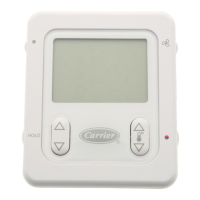
If the compressor won't run, it could be due to several reasons. First, the overload might be open, in which case you should check and correct the cause. Another possibility is that the pump motor is off, so you should start it. Check the thermostat settings and set it properly if it's too high. Also, low line voltage could be the issue, so check and correct it. Finally, safety devices might be open; in that case, check the cause and reset them.