Do you have a question about the Carrier 50DD028 and is the answer not in the manual?
Inspect unit for transportation damage, file claims, keep upright.
Assemble and install accessory roof curb as described in instructions.
Provide a level concrete slab extending beyond unit cabinet at least 6 inches.
Unit condenser air inlets and outlets may be located in any compass direction.
Unit is shipped set up for thru-the-bottom duct connections.
Modifications required to convert unit for thru-the-side duct connections.
Ductwork may not be connected thru-the-side due to economizer interference.
Units may be connected to ductwork thru bottom or side.
Refer to Fig. 9 and 12 and perform the following procedure for conversion.
Install a jumper on economizer terminal block terminals 7 and 8.
Install a jumper on unit economizer terminals 2 and 3.
Install accessory relief air damper and hood as described in installation instructions.
Install hood assemblies over exhaust air openings.
Check return air filters of correct type and size are installed in unit filter racks.
Ensure all outdoor air inlet screens are in place before operating unit.
Condensate drain is open to atmosphere and must be trapped.
If drain line is required, install a separate one.
For cooling only units, provide a fused disconnect switch.
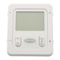
Install a Carrier approved accessory thermostat assembly.
Unit operation is programmed by a control panel adjacent to the indoor air fan motor.
Unit and room thermostat factory wired to provide 2-stage heat.
Loosen compressor hold-down bolts until slight sidewise movement is obtained.
Open the liquid line service valves.
Remove shipping bracket from indoor air fan motor.
Fans, belts and pulleys are installed and adjusted at the factory.
Open compressor service valves. Check oil level. Set system selector to "Cool".
Check cooling effect at duct supply outlets.
Turn on unit power; set circuit breakers at "On." Set system selector switch at "On."
Unit will automatically switch from heating to cooling mode based on space temperature.
Unit with modulating outdoor air control should operate as described.
Set outdoor air thermostat in unit control box to desired temperature.
Dampers will assume ventilation position when indoor air fan is operating.
Dampers assume ventilation position when indoor fan is operating.
Outdoor air damper remains closed; no outdoor air introduced.
Unit operates with free cooling when outdoor temp is below OAT setting.
Exhaust fan discharges return air proportional to outdoor air quantity.
Timer sequence provides a 5-minute delay in compressor start-up.
Unit main power supply must remain on for crankcase heater operation.
Shut off unit power, remove access cover, and relocate panel if needed.
Turn on unit power, set controls, and check operation.
Diagram showing unloader locations on compressor.
Factory settings are On 6:30 AM; Off 7:30 PM. Adjust trippers as needed.
Monitors conditioned air temperature, operates cam switches to load/unload compressor.
Drives cams to activate snap-acting switches for capacity control.
Switches are factory set; reset as required for angular differential and between switches.
Adjust switch settings using a specific procedure for alignment and differential.
Fan motor pulley is factory set for fan speed. Adjust for different speeds.
Fixed fan speeds are set. Select field-supplied motor or pulleys if other speeds are needed.
Shut off power, loosen bolts, remove belt, use bushing bolts to loosen bushing.
Loosen pulley setscrews, slide pulley along shaft, adjust angular alignment.
Loosen pivot bolts, adjust tension for proper deflection, tighten bolts.
Adjust belt tension for proper deflection.
Shut off power, remove guard, adjust fan height.
Set outdoor air thermostat high, install jumper, remove control relay.
Turn adjustment screw slowly until dampers assume desired vent position.
Dampers do not have spring return; remain in position until power is restored.
Use standard evacuating procedures, weigh in specified amount of refrigerant.
Restrict condenser air flow, add refrigerant until sight glass clears.
Use standard evacuating procedures, weigh in specified amount of refrigerant.
Restrict condenser air flow to maintain pressure, add refrigerant until sight glass clears.
Evacuate system, weigh in specified amount of refrigerant.
Use charging chart, add refrigerant until sight glass clears.
| Brand | Carrier |
|---|---|
| Model | 50DD028 |
| Category | Accessories |
| Language | English |