selections. See Fig. 1-3 for unit identification.
Fig. 1 — Unit Identification
LEGEND
Fig. 2 — 39L Model Number
CV — Constant Volume
DX — Direct Expansion
VAV — Var iable Air Volume
Due to the complexity of the (18 position) 39L model number, use the “verify model number”
function in the AHUBuilder® software for a detailed model explanation. The description below
can be used as a general model guide.
Pos. 1-3: Unit Type — 39L Air Handler
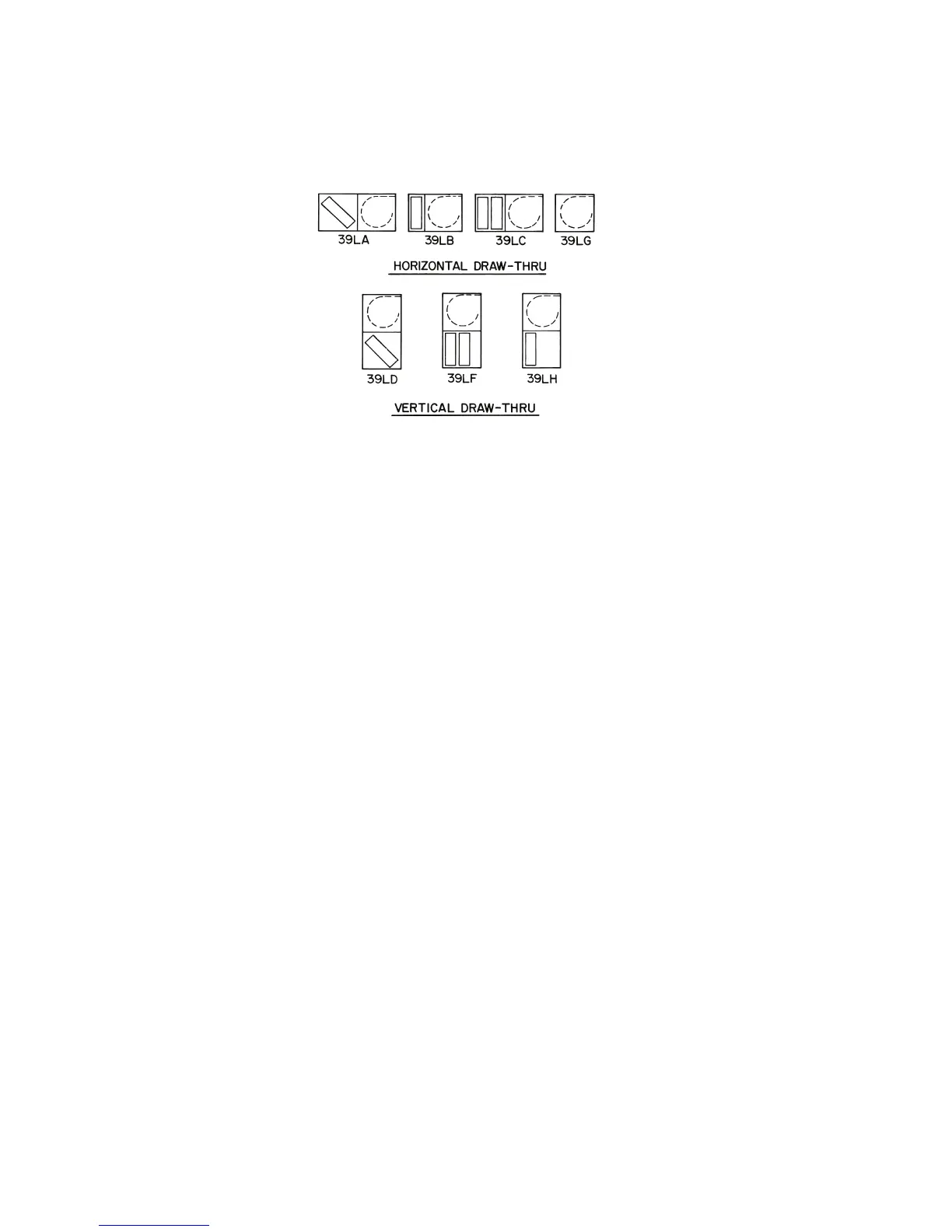
Pos. 4: Unit Model — how the unit is configured. Refer to Fig. 3.
Pos. 5-6: Unit Size — Ranges from 03 to 25.
Pos. 7-8: Draw-Thru Options — Includes the sections that will make up the unit.
Pos. 9-12: Coil Type and Arrangement — Describes the coil type (chilled water, CX, heating
only, etc.), fins, rows and circuit information.
Pos. 13-15: Fans — Describes fan discharge, fan speed, and motor information.
Pos. 16: Controls — Describes the AirManager™ control offering (CV, VAV) and the
components that they include.
Pos. 17: F1/F2 Motors — Depending upon positions 13 and 17, F1 or F2 motors may be
substituted for top mounted motor conduit boxes.
Pos. 18: Special Order — Allows copper fin coils and/or .025 in. wall tubes.