11
G
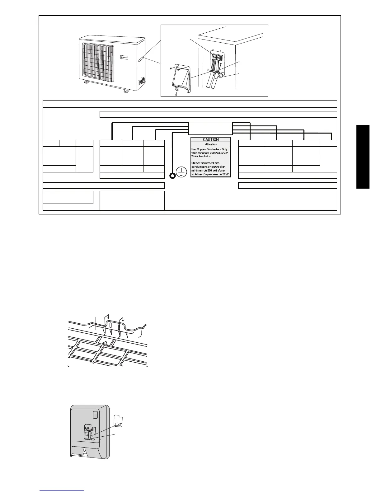
Terminal Block
Conduit panel
Conduit
Outdoor unit
Covered conduit connection for size 18k only
L1 L2 GND L2 S L1 L2 S L1 GND
Ground Ground
208/230 Low V DC 208/230 208/230 Low V DC 208/230
Power and Control Signal to
Indoor Units
Two - Five Terminal Blocks
Control from
Outdoor Unit
Outdoor Unit Terminal Blocks
38GVM-40GVM 18K - 42K Connection Diagram
This Series of Connections Will be Repeated for Each Indoor Unit (A to A - B to B etc.)
CONNECTING CABLE
OUTDOOR TO INDOOR
Indoor Unit Terminal Block (1)
A12558
Fig. 16 --- Field Wiring
INSTALL ALL POWER, INTERCONNECTING
WIRING, AND PIPING TO INDOOR UNIT.
1. Run interconnecting piping and wiring from outdoor unit to
each indoor unit (in matched pairs).
2. Pass interconnecting cable through hole in wall (outside to
inside).
3. Lift indoor unit into position and route piping and drain
through hole in wall (inside to outside). Fit interconnecting
wiring into back side of indoor unit.
4. Hang indoor unit on upper hooks of wall mounting plate (as
shown in Fig. 17)
A08283
Fig. 17 --- Hanging Indoor Unit
5. Open front cover of indoor unit and remove field wiring ter-
minal block cover (see Fig. 18)
Field Wiring
Cover
Interconnecting
Cable
A08279
Fig. 18 --- Field Wiring Cover
6. Pull interconnecting wire up from back of indoor unit and
position in close to the terminal block on indoor unit.
7. Push bottom of indoor unit onto mounting plate to com-
plete wall mount.
8. Connect wiring from outdoor unit per connection diagram
(see Fig. 16).
NOTE: Polarity of power wires must match original
connection on outdoor unit.
9. Replace field wiring cover and close front cover of indoor
unit.
10. Connect refrigerant piping and drain line outside of indoor
unit. Refer to Piping Connections to Outdoor Unit section
and Fig. 14 for proper installation of flare connections.
Complete pipe insulation at flare connection then fasten pip-
ing and wiring to the wall as required. Completely seal the
hole in the wall.
11. Repeat steps 1 through 10 for each indoor unit.
38/40GVM
 Loading...