2740KMC---N
English
Suomi
Fig.1.
A - Unit
B - Frame / Grille assembly
Fig.15.
Heat pump: louvre position for correct air flow
Cooling: louvre position for correct air flow
Fig.18.
Nut
Wooden frame
Threaded hangers
Washers
Nut
Washer
Threaded hangers
Washer
Nut
Nut
Fig.19.
Threaded hangers
"T" bar (to be removed)
Fig.20.
Threaded hangers
"T" bar (to be removed)
Suspension brackets
Fig.21.
False ceiling
Spirit level
Fig.22.
Indoors
Outdoors
Fig.25.
- Frame support brackets
Fig.26.
- Power connection cables from frame
- Power connection cables from unit
- Safety cord
- Cable clamp
- Frame support screws
Fig.28.
- Gasket "A"
- Gasket "B"
Fig.33.
- Pipe
- Pipe insulation
- Adhesive tape
Fig.35.
- Condenser (under main terminal board)
- Ground connection screws
- GMC board
- Outdoor unit connection terminal board
- Relay board (only on models with electric
heater)
- Transformer
- Holes for fixing panel in position
- Emergency push-button
Fan connector
LED/RECEIVER connector
Float connector
Pump connector
Louvre connector
C. Electric heater supply connection
D. Outdoor unit connection
Fig. 38 - 39 - 40 - 41 - 42 - 43 - 44 - 45.
Earth
L Live power supply
N Neutral power supply
N Neutral connection indoor / outdoor unit
Y Compressor interlocking
O Reversing valve control
W2 Outdoor fan signal
R Live connection indoor / outdoor unit
C Neutral connection indoor / outdoor unit
S Defrost and signal
Power supply cable (H07 RN-F)
AA
AA
A
Interconnection cable (H07 RN-F)
Interconnection cable (H07 RN-F)
Interconnection cable (H07 RN-F)
Interconnection cable (H07 RN-F)
Interconnection cable (H07 RN-F)
Notes:
• See outdoor unit installation manual.
• For correct passage of cables,
please refer to the drawing shown at the end
of this section.
c Cooling only
d Heat pump
e Model
f Indoor and outdoor units interconnection
(mm
2
)
g Disconnected
h Combined with Multisplit
i Connected to a multisplit unit
Fig.46.
Wiring diagram - Cooling only or heat pump
units with electric heater
Factory wiring
Field wiring
Connector
Terminal on component
Terminal on strip
Normally close contact
Normally open contact
Capacitor
Sensor
Transformer
FC Fan capacitor
FS Safety micro float
IFM Indoor fan motor
PS Drain pump
T Transformer
C1 LED/IR board connector
C2 Float connector
C3 Fan motor connector
C4 Louvre motor connector
C5 Pump connector
*LM Louvre motor
*MSLMicroswitch louvre
PCB Relay board
HTR Electric heater
ST Safety Thermostat
* If present
R- Live power supply
C- Neutral power supply
A/C Cooling only
H/P Heat pump
60Hz Special Exsport Market
Wire colours
Brown
Blue
Black
Grey
Yellow / Green
Orange
Red
White
Yellow
Important: the warranty will be invalidated, if
factory wiring and settings are field-changed.
Note 2: The electric heater power supply cable
must be of the 5G2.5 H07 RN-F type.
Fig.47.
Cable passage
Power supply cable
Interconnection cable
Interconnection cable
Electric heaters power supply cable
(optional)
Room Controller/CZM connecting cable
(optional). Refer to the control manual.
Fig.48.
Duct connection flange
Clip
6 mm neoprene gasket
Insulated flexible duct
Fresh air intake
Conditioned air supply to an adjacent room
Polystyrene partition
Baffle
Frame
Fig.49.
Air intake grille
Wall
Undercut door
Wall-fitted grille
Door-fitted grille
Fig.50.
Diagram of conditioned air supply to an
adjacent room: one louvre closed
Supply air duct to adjacent room
- Air flow
- External static pressure - Pa
Fig.51.
Warning lamps and emergency button
P : Green LED
Q : Red LED
R : Yellow LED
S : Remote control signal receiver
T : “Emergency”
AA
AA
A
BB
BB
B
CC
CC
C
GG
GG
G
OO
OO
O
RR
RR
R
WW
WW
W
YY
YY
Y
YGYG
YGYG
YG
CP
CA
CG
LegendLegend
LegendLegend
Legend
CV
CLR
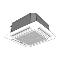
Split system “Global cassette” indoor unit
The unit can be used with infrared Remote Control, with the Carrier “Room Controller” or “Zone Manager”.
Infrared control installation instructions are contained in the unit instruction and maintenance manual.
Remote controls intallation instructions are contained in the relevant manuals, supplied with the remote controls. The operation and
maintenance instructions for the indoor unit and the installation instructions for the indoor and the outdoor unit are given in the
manuals for each unit. These are supplied with the unit.
IR Remote Control “Room Controller” “Zone Manager”
 Loading...