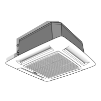
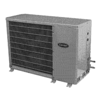
40KMC---N
GB - 10
IMPORTANT for units equipped with electric heater:
The unit is equipped with two thermostats: one with automatic reset
and one with manual (electric) reset that can be reactivated by
switching the power supply off and then on.
Electrical connections
CONTROL PANEL
mod. 12 - 18 - 24
Control panel can be reached by opening the grille and removing its
metal cover by 4 screws.
CA
CLR
CV
C G
CP
A
B
Condenser
(under main terminal
board)
Ground connection screws
GMC board
Outdoor unit connection
terminal board
CV
CP
CG
CA
CLR
A
B
Relay board (only on
models with electric
heater)
Transformer
Holes for fixing panel in
position
Emergency push-button
Fan connector
LED/RECEIVER connector
Float connector
Pump connector
Louvre connector
A. Electric heater supply
connection
B. Outdoor unit connection
CP
CG
CA
CV
CLR
CONTROL PANEL
mod. 28 - 36 - 48 - 60
SYSTEM CONFIGURATION
IMPORTANT:
• Make ground connection prior to any other electrical
connections.
• If the is fitted with an electric heater, this must have a separate
power supply.
• Make the electrical connections between units prior to proceeding
to the main supply unit connection.
• According to the installation instructions, the disconnecting
switches from the mains power supply should have a contact gap
(4 mm) such that total disconnection can be ensured under the
conditions provided for by overvoltage class III.
• Make sure the electric heaters power supply cable is fixed as
shown in the figure CABLE PASSAGE (see page 14).
Make certain that the YELLOW/GREEN cable is stripped back
further than the others.

 Loading...


