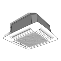
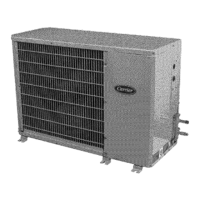
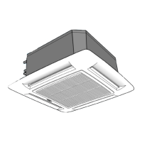
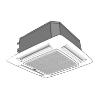
40KMC---N
GB - 3
ENGLISH
Technical data
Note: For power supply wire size and delay type fuses, refer to the outdoor unit installation instructions.
Table I: Nominal data
POWER INPUT (WATT)
Cooling only
Sizes standard Cooling Heating
12 40KMC012-7N 75 75
18 40KMC018-7N 80 80
24 40KMC024-7N 105 105
28 40KMC028-7N 107 107
36 40KMC036-7N 131 131
48 40KMC048-7N 178 178
60 40KMC060-7N 231 231
Sizes with electric heaters Cooling Heating
12
40KMC112-7EN
75 1575
18
40KMC118-7EN
80 2580
24
40KMC124-7EN
105 2605
28
40KMC328-7EN
107 3107
36
40KMC336-7EN
131 3131
48
40KMC348-7EN
178 3178
60
40KMC360-7EN
231 3231
POWER INPUT (WATT)
Heat pump
Sizes standard Cooling Heating
12 40KMC012-7N 75 75
18 40KMC018-7N 80 80
24 40KMC024-7N 105 105
28 40KMC028-7N 107 107
36 40KMC036-7N 131 131
48 40KMC048-7N 178 178
60 40KMC060-7N 231 231
Sizes with electric heaters Cooling Heating
12
40KMC112-7EN
75 1575
18
40KMC118-7EN
80 1580
24
40KMC124-7EN
105 1605
28
40KMC328-7EN
107 2107
36
40KMC336-7EN
131 2131
48
40KMC348-7EN
178 2178
60
40KMC360-7EN
231 2231
Table II: Technical data of electric heaters (if installed)
Heat pump Cooling only
Mod. 12 18 24 28 36 48 60 12 18 24 28 36 48 60
Electric heater kW 1.5 1.5 1.5 2 x 1.0 2 x 1.0 2 x 1.0 2 x 1.0 1.5 1.5 1.5 2 x 1.0 2 x 1.0 2 x 1.0 2 x 1.0
++++++
capacity
1.0 1.0 2 x 0.5 2 x 0.5 2 x 0.5 2 x 0.5
Supply voltage V 230 230 230 230 230 230 230 230 230 230 400 400 400 400
(*) (*) (*) (*) (*) (*) 3N 3N 3N 3N
Max. current draw A 6.5 6.5 6.5 8.8 8.8 8.8 8.8 6,5 10.8 10.8 7.5 7.5 7.5 7.5
Control device GMC electronic control
Safety thermostat
N° 1
Manual reset thermostat
ST1 60°C
N° 1
Manual reset thermostat
ST2 100°C
Power supply cables mm
2
3 G 1.5 3 G 1.5 3 G 1.5 4 G 1.5 4 G 1.5 4 G 1.5 4 G 1.5
3 G 1.5 3 G 2.5 3 G 2.5 5 G 1.5 5 G 1.5 5 G 1.5 5 G 1.5
Recommended fuse (gL type) A 88888888121210101010
*
In areas with a 2 kW limit for single-phase electric heaters it is possible to divide the power supply on two phases and neutral of a three phase supply with neutral.
Use cable type
H07 RN-F - 4G1,5 mm
2
- 400V 2N ~
Table III:
Material supplied
Description Quantity Use
Installation instructions 1 Indoor unit installation
Owner's Manual 1 Correct use
Fresh air intake baffle 1 Air renewal
Table IV: Operating limits
Cooling / Heating Refer to outdoor unit installation manual.
Nominal single-phase voltage 230V
~
50Hz 230V-240V
~
60Hz
Main power supply Operating voltage limits min. 198V – max. 264V
Nominal three-phase voltage 400V 3N
~
50Hz
Operating voltage limits min. 342V – max. 462V
Electric heater 27
°C
Table V: Components required for a complete installation
Name Specification
Connection pipe
40KMC 012N Ø (1/2") 12.70 mm (Gas) / Ø (1/4") 6.35 mm (Liquid)
40KMC 018N, 024N, 028N, 036N, 048N and 060N Ø (1/2") 12.70 mm (Gas) / Ø (1/4") 6.35 mm (Liquid)
Wall sleeve
Wall cap
Finishing tape PVC
film
Fastening tape
Tube insulation
Drain hose
I.D. 16 - 17 mm
Sealer putty
- Outdoor power supply cable H07 RN-F (60245IEC66),
cable with synthetic rubber insulation and polychloroprene sheath.
- Electrical connecting cable H07 RN-F (60245IEC66),
between indoor and outdoor unit cable with synthetic rubber insulation and polychloroprenesheath.

 Loading...


