12
INSTALL ALL POWER, INTERCONNECTING
WIRING, AND PIPING TO THE INDOOR UNIT
1. Run interconnecting piping and wiring from the outdoor
unit to the indoor unit.
2. Run an interconnecting cable through the hole in wall
(outside to inside).
3. Lift the indoor unit into position and route piping and drain
through the hole in wall (inside to outside). Fit the
interconnecting wiring into the back side of the indoor unit.
4. Put an upper claw at the back of the indoor unit on the up-
per hook of the Mounting Plate, move the indoor unit from
side to side to ensure it is securely hooked.
5. Open the indoor unit’s front cover and remove the field
wiring terminal block cover.
6. Pull the interconnecting wire up from the back of indoor
unit and position close to the terminal block on the indoor
unit.
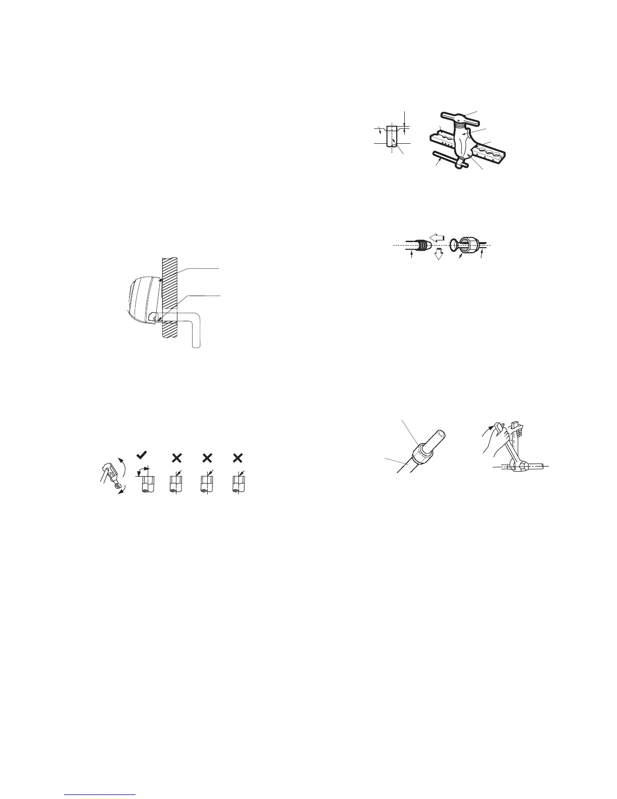
7. Push the lower part of the indoor unit up on the wall, then
move the indoor unit from side to side, up and down to
ensure it is hooked securely (see Fig. 13).
Upper hook
Lower hoo
Fig. 13 - Indoor Unit Installation
8. Connect the wiring from the outdoor unit per the
connection diagram (see Fig. 10 and Fig. 12).
9. Replace the field wiring cover and close the front cover of the
indoor unit.
10. Piping:
a. Cut the pipe, with a pipe cutter, at 90 degrees (see Fig. 14).
b. Remove the service connection, if provided with the unit.
Oblique
DŽ
90
Roughness
Burr
A150767
Fig. 14 - Pipe Cutting
c. Remove all the burrs from the cut cross section of the pipe
avoiding any burrs inside the tubes.
d. Remove the flare nuts attached to the indoor and outdoor
units.
e. Install the correct size flare nut onto the tubing and make
the flare connection. Refer to Table 6 for the flare nut
spaces.
Table 6—Flare Nut Spacing
OUTER DIAM. (mm)
A (mm)
Max. Min.
Ø 1/4" (6.35) 0.05 (1.3) 0.03 (0.7)
Ø 3/8" (9.52) 0.06 (1.6) 0.04 (1.0)
Ø 1/2" (12.7) 0.07 (1.8) 0.04 (1.0)
Ø 5/8" (15.88) 0.09 (2.2) 0.08 (2.0)
Bar
Copper pipe
Clamp handle
Red arrow mark
Cone
Yoke
Handle
Bar
"A"
Fig. 15 - Flare Nut Spacing
f. Apply a small amount of refrigerant oil to the flare
connection on the tubing.
g. Align the center of the pipes and/or service valve.
Indoor unit tubing Flare nut Piping
A150769
Fig. 16 - Align Pipe Center
h. Connect both the liquid and gas piping to the indoor unit
i. Tighten the flare nut using a torque wrench as specified in
Table 7.
Table 7—Tightening Torque
PIPE DIAMETER
INCH (mm)
TIGHTENING TORQUE
Ft-lb N-m
Ø1/4” (6.35) 10 to 13 13.6 to 17.6
Ø3/8” (9.52) 24 to 31 32.5 to 42.0
Ø1/2” (12.7) 37 to 46 50.1 to 62.3
Ø5/8” (15.88) 50 to 60 67.7 to 81.3
Flare nut
Copper tube
A150770
Fig. 17 - Tighten the Flare Nut

 Loading...