Service Manual
40MAQ / 38MAQ
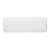
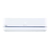
High- W a ll Du ctl es s S pl it System
Sizes 09 to 30
TABLE OF CONTENTS
PAGE
SAFETY CONSIDERATIONS 1.........................
INTRODUCTION 1...................................
MODEL / SERIAL NUMBER NOMENCLATURE 2.........
STANDARD FEATURES AND ACCESSORIES 3...........
SPECIFICATIONS (HEAT PUMP ONLY UNITS) MAQ 4.....
DIMENSIONS - INDOOR 5............................
DIMENSIONS - OUTDOOR 6..........................
CLEARANCES - INDOOR 9...........................
CLEARANCES - OUTDOOR 9.........................
WIRING 10..........................................
CONNECTION DIAGRAMS 11.........................
WIRING DIAGRAMS 12...............................
FAN AND MOTOR SPECIFICATIONS 17.................
SOUND DATA SPECIFICATION 17......................
REFRIGERATION CYCLE DIAGRAM 21.................
REFRIGERANT LINES 21.............................
SYSTEM EVACUATION AND CHARGING 22.............
CONTROL S YSTEM 24...............................
SEQUENCE OF OPERATION 25........................
MODES OF OPERATION 25............................
TROUBLESHOOTING 29..............................
APPENDIX 61.......................................
SAFETY CONSIDERATIONS
Installing, starting up, and servicing air- conditioning equipment
can be hazardous due to system pressures, electrical components,
and equipment location (roofs, elevated structures, etc.).
Only trained, qualified installers and service mechanics should
install, start- up, and service this equipment.
Untrained personnel can perform basic maintenance functions such
as cleaning coils. All other operations should be performed by
trained service personnel.
When working on the equipment, observe precautions in the
literature and on tags, stickers, and labels attached to the
equipment.
Follow all safety codes. Wear safety glasses and work gloves. Keep
quenching cloth and fire extinguisher nearby when brazing. Use
care in handling, rigging, and setting bulky equipment.
Read thi s manua l thoroughly and follow a ll warni ngs or cautions
included in literature and attached to the unit. Consult local building
codes a nd National Ele ctr ical Code (NEC) for s pe cial r equirem ents .
Recognize sa fety inf orma t ion. This i s t he safety- alert sym bol
!
!
.
Whe n you see this symbol on the unit and in instr uctions or manuals,
be a lert t o t he pote ntial f or pe rsonal i njury. Under stand these s ignal
words: DANGER, WARNING, and CAUTI ON.
These words are used with the safety- alert symbol. DANGER
identifies the most serious hazards which will result in severe
personal injury or death. WARNING signifies hazards which could
result in personal injury or death. CAUTION is used to identify
unsafe practices which may result in minor personal injury or
product and property damage. NOTE is used to highlight
suggestions which will result in enhanced installation, reliability, or
operation.
!
WARNING
ELECTRICAL SHOCK HAZARD
Failure to follow this warning could result in personal
injury or death.
Before installing, modifying, or servicing system, main
electrical disconnect switch must be in the OFF
position. There may be more than 1 disconnect switch.
Lock out and tag switch with a suitable warning label.
EXPLOSION HAZARD
Failure to follow this warning could
result in death, serious personal injury,
and/or property damage.
Never use air or gases containing
oxygen for leak testing or operating
refrigerant compressors. Pressurized
mixtures of air or gases containing
oxygen can lead to an explosion.
!
WARNING
CAUTION
!
EQUIPMENT DAMAGE HAZARD
Failure to follow this caution may result in equipment
damage or improper operation.
Do not bury more than 36 in. (914 mm) of refrigerant pipe
in the ground. If any section of pipe is buried, there must be
a 6 in. (152 mm) vertical rise to the valve connections on
the outdoor units. If more than the recommended length is
buried, refrigerant may migrate to the cooler buried section
during extended periods of system shutdown. This causes
refrigerant slugging and could possibly damage the
compressor at start- up.
INTRODUCTION
This Se r vice Manual pr ovi des the necess ary informa t ion to service,
repair, and maintain the 38- 40MA family of Puron air conditioners
and hea t pumps . Se ction 2 of this ma nual has an appe ndi x wit h dat a
required to perform tr oubleshooting. Use the Ta ble of Contents to
locate a desired topic.