11
ELECTRICAL DATA
Table 5—Electrical Data
HIGH WALL UNIT
SIZE
INDOOR FAN
MAX FUSE CB AMP
V-Ph-Hz FLA HP
9K
115-1-60
0.33 0.053
Refer to outdoor unit installation instructions –
Indoor unit powered by the outdoor unit
12K 0.33 0.053
9K
208/230-1-60
0.33 0.053
12K 0.33 0.053
18K 0.49 0.067
24K 0.61 0.16
30K 0.61 0.16
36K 0.61 0.16
LEGEND
FLA - Full Load Amps
CONNECTION DIAGRAMS
S
L
N
115-1-60
Main
Power Supply
115-1-60
L
N
S
L
N
Power to
Indoor Unit
CONNECTING CABLE
OUTDOOR TO INDOOR
GND
Ground
Indoor
Signal
High
Voltage
115-1-60
115-1-60
FIELD POWER SUPPLY
GND
Indoor
Signal
High
Voltage
Indoor Unit
Power Supply
S
L1 L2
208/230-1-60
Main
Power Supply
L1
L2
S
L1
L2
CONNECTING CABLE
OUTDOOR TO INDOOR
Indoor Unit
Power Supply
208/230-1-60
Indoor
Signal
High
Voltage
GND
Ground
Power to
Indoor Unit
Indoor
Signal
High
Voltage
208/230-1-60
FIELD POWER SUPPLY
GND
208/230-1-60
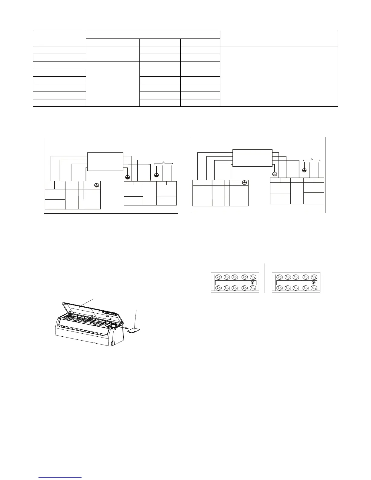
9K and 12K 115V Indoor Unit 9K and 12K 115V Outdoor Unit 9K to 36K 230V Indoor Unit 9K to 36K 230V Outdoor Unit
Fig. 10 - Connection Diagrams
Notes:
1. Do not use thermostat wire for any connection between indoor and outdoor units.
2. All connections between indoor and outdoor units must be as shown. The connections are sensitive to polarity and will result in a fault code.
TERMINAL BLOCK LOCATION
1. Open the indoor unit’s front panel.
2. Using a screwdriver, open the wire box cover on the right
side of the unit, then open the terminal block cover. This
reveals the terminal block.
Electrical box
cover
Front Panel
Fig. 11 - Terminal Block Location
LNS L1 L2 S
9K and 12K 115V 9K to 36K 208/230V
Fig. 12 - Control and Power Wiring on Indoor Unit

 Loading...