15
CONNECTION DIAGRAMS
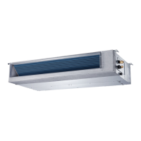
Fig. 35 - Connection Diagrams (Sizes 9−24)
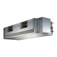
Fig. 36 - Connection Diagrams (Sizes 36−48)
Notes:
1. Do not use the thermostat wire for any connection between indoor and outdoor units.
2. All connections between the indoor and outdoor units must be as shown. The connections are sensitive to polarity and will result in a fault code.
Fig. 37 - Control and Power Wiring on Indoor Unit
INSTALL ALL POWER, INTERCONNECTING
WIRING, AND PIPING TO INDOOR UNIT
1. Run interconnecting piping and wiring from the outdoor
unit to the indoor unit.
2. Connect wiring from the outdoor unit per the connection
diagram (see Fig. 35).
3. Replace the field wiring cover and close the indoor unit
front cover.
4. Connect the refrigerant piping and a drain line outside of
the indoor unit. Complete the pipe insulation at the flare
connection then fasten the piping and wiring to the wall as
required. Completely seal the hole in the wall.
5. Piping:
a. Cut the pipe, with a pipe cutter, at 90 degrees (see Fig. 38).
b. Remove the service connection, if provided with the unit.
Oblique
DŽ
90
Roughness
Burr
Fig. 38 - Pipe Cutting
c. Remove all the burrs from the cut cross section of the pipe
avoiding any burrs inside the tubes.
d. Remove the flare nuts attached to the indoor and outdoor
units.
e. Install the correct size flare nut onto the tubing and make
the flare connection. See Table 6 for the flare nut spaces.
Table 6—Flare Nut Spacing
OUTER DIAM. (mm)
A (mm)
Max. Min.
Ø 1/4" (6.35) 0.05 (1.3) 0.03 (0.7)
Ø 3/8" (9.52) 0.06 (1.6) 0.04 (1.0)
Ø 1/2" (12.7) 0.07 (1.8) 0.04 (1.0)
Ø 5/8" (15.88) 0.09 (2.2) 0.08 (2.0)
Bar
Copper pipe
Clamp handle
Red arrow mark
Cone
Yoke
Handle
Bar
"A"
Fig. 39 - Flare Nut Spacing
f. Apply a small amount of refrigerant oil to the flare
connection on the tubing.
g. Align the center of the pipes and/or service valve.

 Loading...