40MBFAQ: Service Manual
Manufacturer reserves the right to change, at any time, specifications and designs without notice and without obligations.
21
DIAGNOSIS AND SOLUTION (CONT.)
EH 60/EH 61/EC 53/EC 52/EC 54 (Open Circuit or Short Circuit of Temperature Sensor Diagnosis and Solution)
Description: If the sampling voltage is lower than 0.06V or higher than 4.94V, the LED displays a failure.
Recommended parts to prepare:
• Connection wires
• Sensors
•PCB
Troubleshooting
NOTE: For certain models, the outdoor PCB cannot be removed separately. In this case, the outdoor electric control box should be replaced
as a whole. This images in this manual and the values are only for reference. Actual appearance and values may vary.
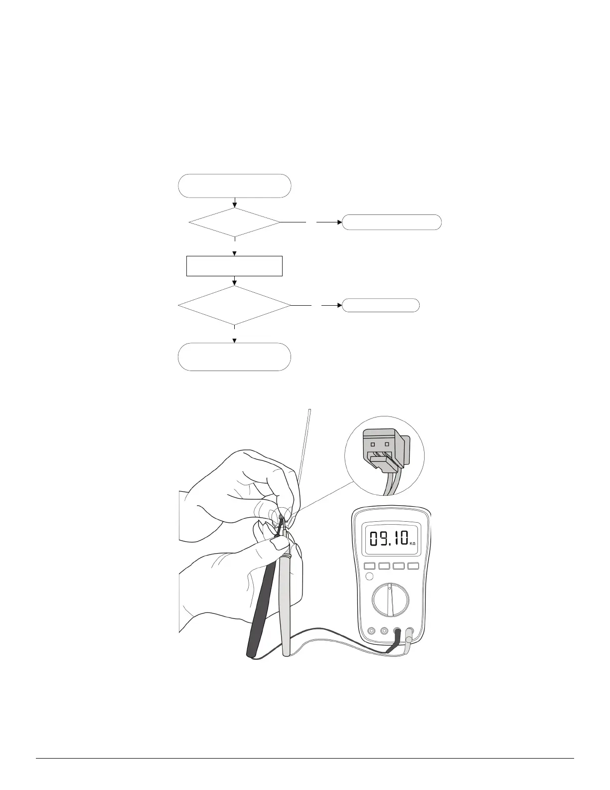
Check the connection between
the temperature sensor and the PCB.
Replace indoor PCB ((E4/E5) or
outdoor PCB (F1/F2/F3)
Is it within acceptable
parameters?
Is it properly wired? Ensure proper connections.NO
Measure the resistance value
of the sensor.
YES
Replace the sensor.NO
YES
 Loading...