27
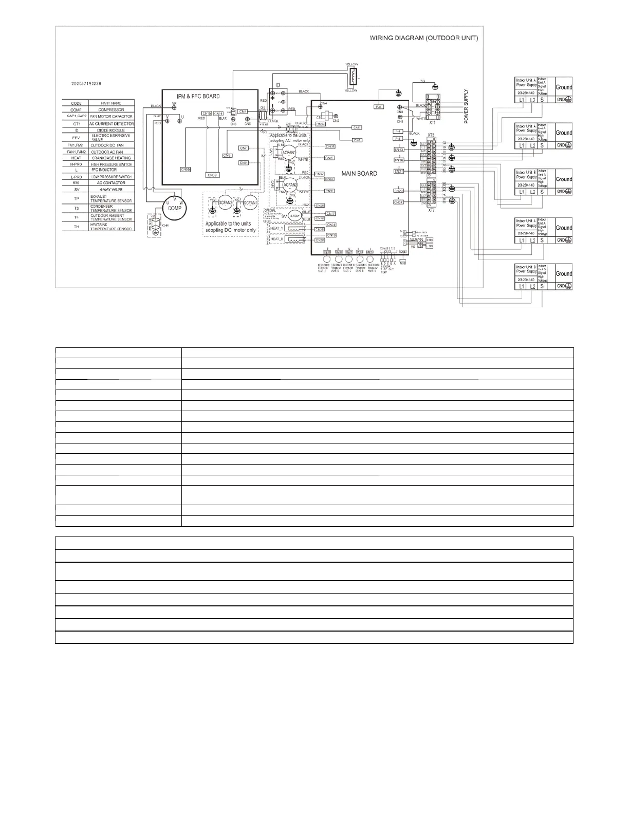
Fig. 22 – Wiring Diagrams 48K
Table 15—Outdoor Unit Control Board Size 48
CODE PAR T NAME
CN1,CN3、P-- 1
Power input: 230V AC
CN2,CN4 Output: Power output for DRIVER BOARD (230V AC)
CN5 Input: Communication Main board and IPM Board ,Pin1(5V DC )
CN6 Input: DC FAN motor1 and DC FAN motor2 control, (Pin7 5 V DC)
CN8,CN9 Input: Temperature sensor(5V DC)
CN10 Input: Pressure test (5V DC)
CN13 Input: Indoor pipe Temperature sensor,Pin1&Pin3&Pin5&Pin7&Pin9&Pin11 (5V DC)
CN15,CN23,CN26, CN30,CN33
Output: PMV control,Pin5(12V DC),Pin6(12V DC)
CN17,CN18 Output: High voltage for 4 --way(SV) control (230V AC)
CN19,CN20 Output: High voltage for HEAT_D control (230V AC)
CN13,CN16,CN21, CN29,CN37 Output: Communication to indoor unit,Pin2 and Pin3 (230V AC ),Pin1 (S, connection to high voltage)
CN24,CN25 Output: High voltage for HEAT_Y control(230V AC)
CN27、CN32、CN34,
CN28、CN31、CN36
Output: Power output for AC FAN motor1 and AC FAN motor2 (230V AC)
CN39
Output: L2 for AC FAN、SV and HEAT ,High voltage (AC)
P--5,P--6 Connection to the earth
OUTDOOR UNIT IPM BOARD
UVW Output: Pulse(0 --380VDC) for COMPRESSOR
CN3
Output: Connect PFC Inductance, high DC voltage
CN6 ,CN8 Input: Power input for DRIVER BOARD (200 --320V DC )
CN7,CN11 Output: DC FAN motor1 and DC FAN motor2 control (Pin1 310V or 380V DC)
CN9 Output: Communication Main board and IPM Board Pin7(5V DC )
CN55 Output: Communication IPM Board and Main board Pin1(12V DC )
CN14、CN15 ---- CN39,
Output: High DC voltage (310V or 380V DC)
 Loading...