7
These installation instructions cover the installation of the matched
systems listed in table 2.
Parts List
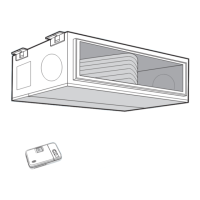
Indoor Unit
The following items are included with the indoor unit:
Table 1 – Installation Materials
Part No. Name of Part Qty.
1 Side Panels 2
2 Hex Head Bolts 4
3 Mounting Bracket 2
4 Pistons 1
5 Installation Template 1
6 Adapter T ubes 2
A09532
Fig. 6 -- Hanging Fan Coil Unit
Outdoor Unit
The following items are included with the outdoor unit:
A09536
Fig. 7 -- 38HDR018--036
A09537
Fig. 8 -- 38QRR018--036
Model Filter Drier
Piston
Cap
Pistons
Flare
Connector
38HDR n --- --- ---
38QRR n n n n
Table 2 – Matched Systems
System
Ty p e
Nominal
Capacity
Outdoor Unit Indoor Unit
Cooling
018 3 8 H D R 0 1 8 --- --- --- 3
4 0 QA C 0 2 4 --- --- --- 3
*
024 3 8 H D R 0 2 4 --- --- --- 3 4 0 Q A C 0 2 4 --- --- --- 3
030 3 8 H D R 0 3 0 --- --- --- 3 4 0 Q A C 0 3 6 --- --- --- 3
036 38HDR036--- --- ---3/5/6 4 0 Q AC 0 3 6 --- --- --- 3
048 38HDR048--- --- ---3/5/ 6 4 0 Q AC 0 4 8 --- --- --- 3
060 38HDR060--- --- ---3/5/ 6 4 0 Q AC 0 6 0 --- --- --- 3
Heat Pumps
Heat Pumps
018 3 8 Q R R 0 1 8 --- --- --- 3 4 0 Q A Q 0 2 4 --- --- --- 3
024 3 8 Q R R 0 2 4 --- --- --- 3 4 0 Q A Q 0 2 4 --- --- --- 3
030 3 8 Q R R 0 3 0 --- --- --- 3 4 0 Q A Q 0 3 6 --- --- --- 3
036 38QRR036--- --- ---3/5/ 6 4 0 Q AQ 0 3 6 --- --- --- 3
048 38QRR048--- --- ---3/5/ 6 4 0 Q AQ 0 4 8 --- --- --- 3
060 38QRR060--- --- ---3/5/ 6 4 0 Q AQ 0 6 0 --- --- --- 3
* Units must be configured for 1---1/2 ton operation. Refer to instructions
on page 9.
SYSTEM REQUIREMENTS
Clearances
Allow sufficient space around the indoor and outdoor unit for
proper airflow circulation and servicing. Refer to Fig. 1 through
Fig. 5 for minimum required clearances.
Piping: Piping and insulation is field supplied.
Piping Lengths
The minimum length between the indoor and outdoor units is 10 ft
(3 m). Refer to table 3 for the maximum lengths allowed.
Table 3 – Maximum Refrigerant Line Lengths
Unit
Size
Max Line
Length ft(m)
Max Elevation (ID
over OD) ft(m)
Max Elevation (OD
over OD) ft(m)
18K 200 (61) 65 (19.8) 200 (61)
24K 200 (61) 65 (19.8) 200 (61)
30K 200 (61) 65 (19.8) 200 (61)
36K 200 (61) 65 (19.8) 200 (61)
48K 200 (61) 65 (19.8) 200 (61)
60K 200 (61) 65 (19.8) 200 (61)
Note:For lengths greater than 25 ft (7.6 m), refer to the Duct Free Long
Line Guide.
Pipe Sizes
Refer to table 4 for pipe sizes.
Table4–PipeSizes
PIPE SIZES (in)
Unit Size Liquid Phase
Vapor
38HDR 38QRR
18 3/8 5/8 5/8
24 3/8 5/8 5/8
30 3/8 3/4 3/4
36 3/8 3/4 3/4
48 3/8 7/8 3/4
60 3/8 7/8 3/4
Note: On heat pumps, both lines need to be insulated using at least 1/2 inch
closed foam insulation.
40QAC/38HDR -- 40QAQ/38QR

 Loading...