13
Condensate Drain
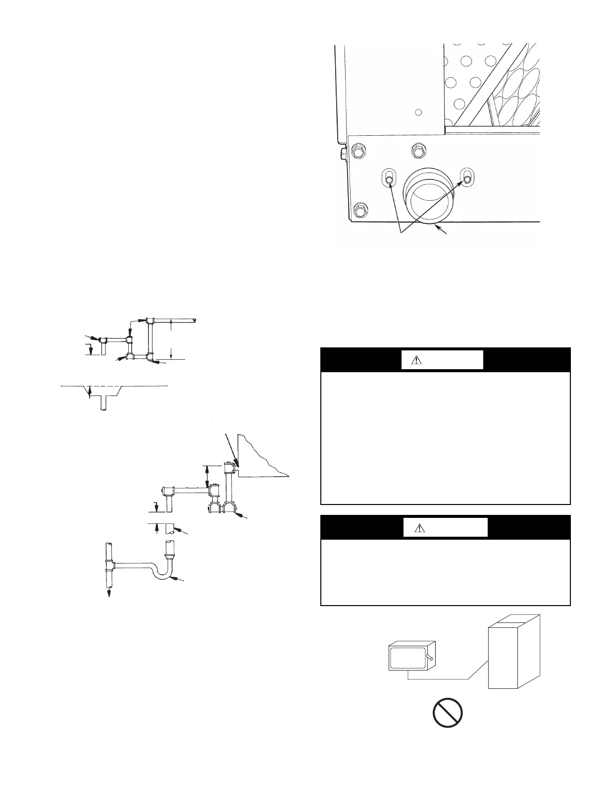
Install a trapped condensate drain line to unit connection as shown
in Fig. 11. The unit drain connection is a PVC stub. (See Fig. 12.)
Some areas may require an adapter to connect to either galvanized
steel or copper pipe. For these applications, install a field-supplied
threaded PVC adapter.
NOTE: A trap must be installed in the condensate drain line to en-
sure that the static pressure of fans is balanced with the water col-
umn in the drain line and that condensate can drain completely
from pan. Without a trap, air can be drawn up drain line until water
level in condensate pan becomes equal to static pressure created
by fans, preventing complete drainage. Conditions will worsen as
filters become dirty.
Install clean-out plugs in trap. Pitch drain line downward to an
open floor drain or sump. Provide service clearance around drain
line to permit removal of unit panels. Observe all local sanitary
codes.
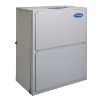
As shipped, the unit’s condensate drain pan is NOT sloped to-
wards the drain connection. The pan slope must be changed to
pitch towards the side of the unit with the drain connection. (See
Fig. 12.) Loosen the 2 screws next to the drain outlet at both ends
of the unit, push drain pan down in the slots near the drain connec-
tion, and up in the slots on the opposite end. Re-tighten screws.
The pan should have a pitch of at least 1/4 in. over its length to-
ward the drain connection.
Fig. 11 — Condensate Drain
Fan Motors and Drives
Motor and drive packages are factory installed in all units. The
motor and drive packages consist of the following items:
1 — ECM fan motor
1 — EcoBlue™ direct drive vane axial fan system
For instructions on setting the fan speed see Supply Fan (Direct
Drive) on page 20.
Fig. 12 — Drain Pan Slope Adjustment
Power Supply and Wiring
Check the unit data plate to ensure that available power supply
matches electrical characteristics of the unit. Provide a disconnect
switch with an integrated lock-out feature of size required to pro-
vide adequate fan motor starting current. See Table 9 for unit
electrical data. See Table 10 for fan contactor coil data.
Fig. 13 — Disconnect Switch and Unit
3” MIN.
[76]
NOTE: Dimensions in [ ] are in millimeters
Plug Plug
3" Min.
[76]
3" Min.
[76]
From
Condensate
Pan
From
Condensate
Pan
Existing Floor
Drain, Sink, or
Hopper
Existing Floor
Drain, Sink, or
Hopper
Unit
Condensate
Conn
Unit
Condensate
Conn
Trap Trap
Not Less Than 18" [457]
Long and Two Sizes
Larger Than Waste Pipe
Not Less Than 18" [457]
Long and Two Sizes
Larger Than Waste Pipe
To Sewer To Sewer
1" Min. 1" Min.
Plug Plug
Plug Plug
3" Min.
[76]
3" Min.
[76]
3" Min.
[76]
3" Min.
[76]
Trap Trap
[25] [25]
Plug Plug
WARNING
Failure to follow this warning could result in personal injury or
death.
Do not use gas piping as an electrical ground.
Unit cabinet must have an uninterrupted, unbroken electrical
ground to minimize the possibility of personal injury if an
electrical fault should occur. This ground may consist of
electrical wire connected to unit ground lug in control
compartment, or conduit approved for electrical ground when
installed in accordance with NEC (National Electrical Code);
ANSI/NFPA 70, latest edition (in Canada, Canadian Electrical
Code CSA [Canadian Standards Association] C22.1), and
local electrical codes.
WARNING
FIRE HAZARD
Failure to follow this warning could result in personal injury,
death, or property damage.
Do not connect aluminum wire between disconnect switch
and fan coil unit. Use only copper wire. (See Fig. 13.)
Adjustment Slots
(Both Ends of Unit)
PVC Stub Unit
Drain Connection
Copper
Wire Only
Electric
Disconnect
Switch
Aluminum
Wire