Do you have a question about the Carrier AquaForce PUREtec 30XAV-ZE 401 and is the answer not in the manual?
Safety precautions for installing chillers in special locations, ensuring proper airflow and access.
Information on storage, operating environment, and pressure vessel considerations.
Guidelines for system maintenance, logbook requirements, and qualified personnel.
Safety measures for repairing units, handling refrigerants, and preventing explosions.
Checking unit condition, completeness, and comparing nameplate data with order details.
Guidelines for safely moving and positioning the unit, considering clearances and support.
Procedures for initiating chiller operation, including pre-start checks and commissioning.
Detailed dimensions and clearances for various 30XAV-ZE models and configurations.
Recommendations for installing multiple chillers to avoid warm air recycling.
Guidelines for maintaining adequate distance to walls for optimal unit operation.
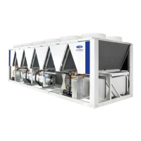
Table detailing physical specifications: sound, dimensions, weight, refrigerant charge, fans.
Table providing electrical specifications: voltage, current draw, power, short-circuit stability.
Detailed electrical specs for each compressor model and their usage per circuit.
Requirements for power supply, voltage imbalance, wire sections, and cable entry.
Information on standard power connection points and disconnect switches.
Precautions and guidance for field wiring of interface circuits and control signals.
Information on power supply reserve and options for user control cabling.
Chiller operating limits, min/max water flow, and pressure drop curves.
Explanation of variable evaporator flow and its system requirements.
Guidance on calculating minimum required water volume for stable operation.
Guidelines for designing and connecting water circuits, including filtering and fluid compatibility.
Details on Victaulic connection sizes and piping limitations for hydronic modules.
Information on flow switches, pump interlocks, freeze protection, and cavitation protection.
Procedure and torque specs for tightening evaporator water box bolts.
Configuration and operation of master/slave assemblies for controlling multiple chillers.
Graphs showing available static pressure for pumps versus flow rates.
Graphs for required NPSH and guidance on flow/capacity calculations.
Details on compressors, oil filter, refrigerant, lubricant, and related components.
Guidelines for pressure vessels, safety switches, condensers, and fans.
Details on EXV, moisture indicator, filter drier, and system sensors.
Information on optional service valves and the function of variable frequency drives.
Options for control box protection, grilles, enclosure panels, and fuse configurations.
Options for evaporator/hydronic freeze protection and master/slave operation.
Details on various hydronic module configurations (HP/LP, single/dual pump).
Options for gateways, Energy Management Module, and Leak Detection.
Options for compliance with Swiss and Russian regulations.
Options for insulation, low noise, anti-corrosion, electrical plug, expansion tank, and variable water flow.
Description of five maintenance levels for HVAC units, emphasizing contract benefits.
Simple checks for users: oil traces, protective devices, alarms, filter cleanliness.
Expert maintenance: tightening connections, differential switches, box cleaning, fan replacement.
Advanced maintenance by manufacturer/agent: component replacement, refrigerant handling.
Torque values for electrical connections, bolts, and screws.
Recommendations for inspecting and cleaning condenser coils.
Checks for evaporator, oil separator, oil filter, and compressor rotation.
Maintenance precautions for VFDs, including isolation and contacting service.
Checklist for installer: preliminary info, equipment details, and shipping damage.
Checklist for verifying unit installation, power supply, wiring, grounding, and connections.
Verification of chilled water pump operation, hydraulic circuit flushing, and strainer.
Checks for oil heaters, valves, leak checks, and voltage imbalance.
Checks for water loop volume, corrosion inhibitor, freeze protection, and strainer.
Checking pressure drop across the cooler and comparing to performance data.
Instructions to report alarms and record special remarks during start-up.
Recording temperatures and pressures after the machine has stabilized.