Manufacturer reserves the right to discontinue, or change at any time, specifications or designs without notice and without incurring obligations.
Catalog No. 04-53300197-01 Printed in U.S.A. Form 30XV-3T Pg 1 6-19 Replaces: New
Controls, Start-Up, Operation, Service
and Troubleshooting
SAFETY CONSIDERATIONS . . . . . . . . . . . . . . . . . . . . . . 2
GENERAL . . . . . . . . . . . . . . . . . . . . . . . . . . . . . . . . . . . . . 3
Conventions Used in This Manual . . . . . . . . . . . . . . . 3
Abbreviations Used in This Manual . . . . . . . . . . . . . 3
CONTROLS . . . . . . . . . . . . . . . . . . . . . . . . . . . . . . . . . . . . 4
Carrier Controller Display . . . . . . . . . . . . . . . . . . . . . 5
Carrier Controller Display User Interface . . . . . . . . . 5
Input/Output (SIOB) Boards . . . . . . . . . . . . . . . . . . . 15
Auxiliary Boards . . . . . . . . . . . . . . . . . . . . . . . . . . . . 17
Enable-Off-Remote Switch (SW1) . . . . . . . . . . . . . . 18
Emergency On/Off Switch (SW2) . . . . . . . . . . . . . . . 18
Energy Management Module (EMM) . . . . . . . . . . . . 18
Local Equipment Network . . . . . . . . . . . . . . . . . . . . 19
Board Addresses . . . . . . . . . . . . . . . . . . . . . . . . . . . 19
Control Module Communication . . . . . . . . . . . . . . . 19
Carrier Comfort Network® Interface . . . . . . . . . . . 19
External Sensor Wiring . . . . . . . . . . . . . . . . . . . . . . . 20
Remote Alarm and Alert Relays . . . . . . . . . . . . . . . . 20
CONFIGURATION (SOFTWARE) . . . . . . . . . . . . . . . . . 20
Carrier Controller Operation Configuration Tables . . 20
Carrier Controller Menu Tables . . . . . . . . . . . . . . . . 20
Machine Control Methods . . . . . . . . . . . . . . . . . . . . 25
Chilled Water Set Point Configuration . . . . . . . . . . 27
Evaporator Pump Control . . . . . . . . . . . . . . . . . . . . 31
Circuit/Compressor Staging and Loading . . . . . . . 32
Dual Chiller Control . . . . . . . . . . . . . . . . . . . . . . . . . 33
Ramp Loading . . . . . . . . . . . . . . . . . . . . . . . . . . . . . . 38
Temperature Reset . . . . . . . . . . . . . . . . . . . . . . . . . . 38
Demand Limit . . . . . . . . . . . . . . . . . . . . . . . . . . . . . . 44
Machine Start Delay . . . . . . . . . . . . . . . . . . . . . . . . . 45
Fast Loading . . . . . . . . . . . . . . . . . . . . . . . . . . . . . . . 45
Ice Storage Operation . . . . . . . . . . . . . . . . . . . . . . . . 46
Broadcast Configuration . . . . . . . . . . . . . . . . . . . . . 46
Alarm Control . . . . . . . . . . . . . . . . . . . . . . . . . . . . . . 46
Daylight Savings Time Configuration . . . . . . . . . . . 47
Capacity Control Overrides . . . . . . . . . . . . . . . . . . . 47
Head Pressure Control (Variable Speed Fans) . . . . 48
Head Pressure Control (Fixed Speed Fans) . . . . . . 49
Sound Optimization . . . . . . . . . . . . . . . . . . . . . . . . . 49
PRE-START-UP . . . . . . . . . . . . . . . . . . . . . . . . . . . . . . . 49
System Check . . . . . . . . . . . . . . . . . . . . . . . . . . . . . . 49
START-UP . . . . . . . . . . . . . . . . . . . . . . . . . . . . . . . . . . . . 49
Actual Start-Up . . . . . . . . . . . . . . . . . . . . . . . . . . . . . 49
Operating Limitations . . . . . . . . . . . . . . . . . . . . . . . .50
OPERATION . . . . . . . . . . . . . . . . . . . . . . . . . . . . . . . . . . .55
Sequence of Operation . . . . . . . . . . . . . . . . . . . . . . .55
Dual Chiller Sequence of Operation . . . . . . . . . . . . .55
Operating Modes . . . . . . . . . . . . . . . . . . . . . . . . . . . .56
Sensors . . . . . . . . . . . . . . . . . . . . . . . . . . . . . . . . . . . .57
SERVICE . . . . . . . . . . . . . . . . . . . . . . . . . . . . . . . . . . . . . .64
Economizer Assembly . . . . . . . . . . . . . . . . . . . . . . . .64
Electronic Expansion Valve . . . . . . . . . . . . . . . . . . .64
Compressor Assembly . . . . . . . . . . . . . . . . . . . . . . .67
Evaporator Service . . . . . . . . . . . . . . . . . . . . . . . . . .68
All Units . . . . . . . . . . . . . . . . . . . . . . . . . . . . . . . . . . .73
MCHX Condenser Coil:
Maintenance and Cleaning . . . . . . . . . . . . . . . . .74
RTPF Condenser Coil:
Maintenance and Cleaning . . . . . . . . . . . . . . . . .74
Condenser Fans . . . . . . . . . . . . . . . . . . . . . . . . . . . . .75
High Static Fan Option . . . . . . . . . . . . . . . . . . . . . . .75
Refrigerant Circuit . . . . . . . . . . . . . . . . . . . . . . . . . . .75
Safety Devices . . . . . . . . . . . . . . . . . . . . . . . . . . . . . .75
Relief Devices . . . . . . . . . . . . . . . . . . . . . . . . . . . . . .76
Variable Frequency Drives . . . . . . . . . . . . . . . . . . . .76
MAINTENANCE . . . . . . . . . . . . . . . . . . . . . . . . . . . . . . .208
Recommended Maintenance Schedule . . . . . . . . .208
TROUBLESHOOTING . . . . . . . . . . . . . . . . . . . . . . . . . .208
Alarms and Alerts . . . . . . . . . . . . . . . . . . . . . . . . . .208
Troubleshooting . . . . . . . . . . . . . . . . . . . . . . . . . . . .223
Electrical Schematics . . . . . . . . . . . . . . . . . . . . . . .226
Quick Test (Service Test) . . . . . . . . . . . . . . . . . . . .226
APPENDIX A — CARRIER CONTROLLER
DISPLAY TABLES . . . . . . . . . . . . . . . . . . . . . . . . . .249
APPENDIX B — CCN POINT TABLE . . . . . . . . . . . . . .281
APPENDIX C — LON POINT TABLE . . . . . . . . . . . . . .308
APPENDIX D — BACNET/MODBUS
TRANSLATOR POINTS . . . . . . . . . . . . . . . . . . . . .309
APPENDIX E — BACNET IP POINTS . . . . . . . . . . . . . .310
APPENDIX F — PIPING AND INSTRUMENTATION . .328
APPENDIX G — MAINTENANCE SUMMARY
AND LOG SHEETS . . . . . . . . . . . . . . . . . . . . . . . . .330
APPENDIX H — EVAPORATOR HEATER SENSOR
SET POINT . . . . . . . . . . . . . . . . . . . . . . . . . . . . . . . .332
APPENDIX I — CARRIER CONTROLLER WEB AND
NETWORK INTERFACE PARAMETERS. . . . . . .333
APPENDIX J — FACTORY SUPPLIED PUMPS . . . . .336
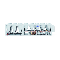
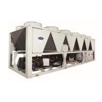
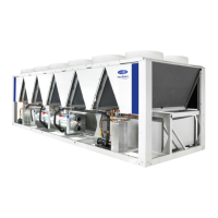
AquaForce
®
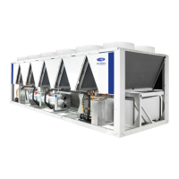
30XV140-500, Series B
Variable Speed Air-Cooled Liquid Chillers
with Greenspeed
®
Intelligence
and Carrier Controller


