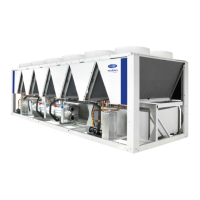
Do you have a question about the Carrier AQUAFORCE 30XA080-500 and is the answer not in the manual?
Essential safety precautions for installing, starting up, and servicing the equipment.
General information about the chiller, including manual conventions and display module usage.
Overview of the electronic control system components and their functions.
Detailed tables for Touch Pilot™ display operation and user configuration settings.
Procedures and checks required for the actual start-up of the chiller unit.
Description of the chiller's sequence of operation and various operating modes.
Description of the standard user interface, its buttons, and navigation.
Description of the mobile user interface, keys, and navigation structure.
Configuration for time/date format and units of measure (US/Metric).
Selection of display language and font.
Adjusting the LCD contrast for optimal visibility.
Setting backlight to remain on or turn off during inactivity.
Adjusting the LCD touch screen calibration.
Configuration of limited and full logged-in access system passwords.
Viewing device information and specifying operating mode.
Configuration of bus and element numbers, and baud rate for network control.
Description of DIP switch 1 (S1) inputs for starter, CT position, and contactor failure.
Addresses for Fan Board A, B, and C DIP switches for unit configuration.
Provides local means for enabling or disabling the machine's operation.
Used for immediate shutdown, interrupting power to all modules.
Receives inputs for temperature reset, set point, and demand limit functions.
Controls hot gas bypass solenoids and pump contactors.
Local control determined by the Start/Stop button on the Touch Pilot display.
Control determined by OPER variable: Switch Control, Time Schedule, or CCN.
Options for controlling the Leaving Chilled Water Set Point.
Configuration for brine or glycol chilled water loops for freeze protection.
Configuration for staging circuits/compressors and their loading sequence.
Enabling and configuring the minimum load control accessory.
Configuration for master/slave operation of two chillers in series or parallel.
Configuration for reducing sound level by limiting fan operation.
Fluid temperature reset based on cooler fluid temperature difference.
Temperature reset based on outdoor-air temperature (OAT).
Temperature reset based on space temperature (SPT).
Temperature reset based on an externally powered 4 to 20 mA signal.
Demand limiting via field-supplied switch for 1-step or 2-step control.
2-step demand limit based on capacity, reducing capacity to set points.
2-step demand limit based on current, limiting capacity to set points.
Demand limit based on unit capacity via 4-20mA signal.
Demand limit based on compressor current via 4-20mA signal.
Demand limit for CCN loadshed control when unit is in CCN control.
Chiller operation configured for making and storing ice.
Configuration for broadcasting OAT, time, date, and holiday status.
Configuration for routing alarms through the CCN.
Main Base Board controls condenser fans to maintain lowest condensing temperature.
Option for low ambient operation using accessory head pressure control.
Description and manual operation of the motorized ball valve in the discharge line.
Determines lead chiller, manages lag chiller operation based on configuration.
Override modes that affect normal equipment operation.
Description and identification of thermistors monitoring chiller operation.
Description of pressure transducers for monitoring chiller operation.
Description of the economizer assembly and its function.
Overview of the EXV, its operation, and control logic.
Steps for diagnosing and correcting EXV problems.
Specifications and procedure for adding oil or a complete charge.
Logic for energizing cooler heaters to prevent freeze-up.
Shuts down chiller if leaving fluid temperature drops below specified limits.
Integral flow switch protects cooler against loss of cooler flow.
Procedure for plugging leaky tubes until retubing.
Function of the factory-installed flow switch in the entering water nozzle.
Steps to complete at the end of the cooling season for winter shutdown.
Procedures for cleaning MCHX condenser coils using high pressure water.
Procedures for routine maintenance and cleaning of RTPF coil surfaces.
Description of the refrigerant circuit and procedures for leak testing and charging.
Description of safety devices protecting the compressor from overcurrent.
Shuts down chiller if leaving fluid temperature drops below specified limits.
Fusible plugs and pressure relief valves designed to relieve abnormal pressure.
Guidelines for routine, monthly, quarterly, and annually maintenance tasks.
Monitoring of unit for abnormal or fault conditions, generating warnings or shutdowns.
Detailed list of alarm codes, reasons, actions, and probable causes.
Alarm triggered if circuit Saturated Suction Temperature is below specified limits.
Alarm triggered if circuit superheat exceeds set point or MOP.
Alarm triggered if circuit superheat is below set point or MOP.
Function to verify proper operation of various chiller devices.
Wiring schematic for low voltage control of 30XA080,082 units.
Wiring schematic for low voltage control of 30XA090-352 units.
Wiring schematic for low voltage control of 30XA400-500 units.
Navigator display table for run status of various parameters.
Navigator display table for service test functions.
Navigator display table for temperature readings.
Navigator display table for pressure readings.
Navigator display table for input status.
Navigator display table for set point configurations.
Navigator display table for output status.
Navigator display table for system configuration settings.
Navigator display table for timeclock schedule configurations.
Navigator display table listing active operating modes.
Navigator display table for active alarms.
CCN table mapping for status display points.
CCN table mapping for configuration settings.
Piping and instrumentation diagram for 30XA080 Flooded Cooler Units.
Piping and instrumentation diagram for multiple 30XA flooded cooler units.
Piping and instrumentation diagram for 30XA082 DX Cooler Units.
Piping and instrumentation diagram for multiple 30XA DX Cooler Units.
Summary of required maintenance intervals for 30XA units.
Log sheet for recording monthly maintenance actions.
Log sheet for recording seasonal shutdown procedures.
Procedure for assigning a unique address to the UPC Open controller.
Settings for the BAS Port DIP switches for MS/TP communication.
Recommendations for wiring the UPC Open controller to the MS/TP network.
Specifications for MS/TP wiring, including cable and vendor recommendations.
Setting CCN Address and Bus Number for ComfortLink and UPC Open.
Indicators for controller communication status.
Troubleshooting common issues with UPC Open controller wiring or addressing.
List of BACnet object identifiers for network points.
List of point names for network communication.
Indicates if network points are readable or writable.
Units of measurement for network points.
Default values for network points.
Allowed range of values for network points.
Project details for the chiller installation.
Contractor checklist for verifying equipment condition before start-up.
Checks for proper installation and operation of the chilled water system.
Steps for testing components and operating the machine.


 Loading...