EasyManua.ls Logo

Carrier AquaForce 30XV275 - User Manual

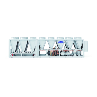
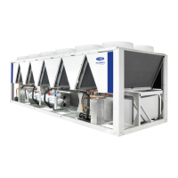
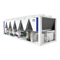
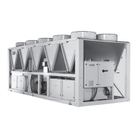
Carrier AquaForce 30XV275
358 pages
Print Icon
To Next Page IconTo Next Page
Loading...
Manufacturer reserves the right to discontinue, or change at any time, specifications or designs without notice and without incurring obligations.
Catalog No. 04-53300197-01 Printed in U.S.A. Form 30XV-3T Pg 1 6-19 Replaces: New
Controls, Start-Up, Operation, Service
and Troubleshooting
SAFETY CONSIDERATIONS . . . . . . . . . . . . . . . . . . . . . . 2
GENERAL . . . . . . . . . . . . . . . . . . . . . . . . . . . . . . . . . . . . . 3
Conventions Used in This Manual . . . . . . . . . . . . . . . 3
Abbreviations Used in This Manual . . . . . . . . . . . . . 3
CONTROLS . . . . . . . . . . . . . . . . . . . . . . . . . . . . . . . . . . . . 4
Carrier Controller Display . . . . . . . . . . . . . . . . . . . . . 5
Carrier Controller Display User Interface . . . . . . . . . 5
Input/Output (SIOB) Boards . . . . . . . . . . . . . . . . . . . 15
Auxiliary Boards . . . . . . . . . . . . . . . . . . . . . . . . . . . . 17
Enable-Off-Remote Switch (SW1) . . . . . . . . . . . . . . 18
Emergency On/Off Switch (SW2) . . . . . . . . . . . . . . . 18
Energy Management Module (EMM) . . . . . . . . . . . . 18
Local Equipment Network . . . . . . . . . . . . . . . . . . . . 19
Board Addresses . . . . . . . . . . . . . . . . . . . . . . . . . . . 19
Control Module Communication . . . . . . . . . . . . . . . 19
Carrier Comfort Network® Interface . . . . . . . . . . . 19
External Sensor Wiring . . . . . . . . . . . . . . . . . . . . . . . 20
Remote Alarm and Alert Relays . . . . . . . . . . . . . . . . 20
CONFIGURATION (SOFTWARE) . . . . . . . . . . . . . . . . . 20
Carrier Controller Operation Configuration Tables . . 20
Carrier Controller Menu Tables . . . . . . . . . . . . . . . . 20
Machine Control Methods . . . . . . . . . . . . . . . . . . . . 25
Chilled Water Set Point Configuration . . . . . . . . . . 27
Evaporator Pump Control . . . . . . . . . . . . . . . . . . . . 31
Circuit/Compressor Staging and Loading . . . . . . . 32
Dual Chiller Control . . . . . . . . . . . . . . . . . . . . . . . . . 33
Ramp Loading . . . . . . . . . . . . . . . . . . . . . . . . . . . . . . 38
Temperature Reset . . . . . . . . . . . . . . . . . . . . . . . . . . 38
Demand Limit . . . . . . . . . . . . . . . . . . . . . . . . . . . . . . 44
Machine Start Delay . . . . . . . . . . . . . . . . . . . . . . . . . 45
Fast Loading . . . . . . . . . . . . . . . . . . . . . . . . . . . . . . . 45
Ice Storage Operation . . . . . . . . . . . . . . . . . . . . . . . . 46
Broadcast Configuration . . . . . . . . . . . . . . . . . . . . . 46
Alarm Control . . . . . . . . . . . . . . . . . . . . . . . . . . . . . . 46
Daylight Savings Time Configuration . . . . . . . . . . . 47
Capacity Control Overrides . . . . . . . . . . . . . . . . . . . 47
Head Pressure Control (Variable Speed Fans) . . . . 48
Head Pressure Control (Fixed Speed Fans) . . . . . . 49
Sound Optimization . . . . . . . . . . . . . . . . . . . . . . . . . 49
PRE-START-UP . . . . . . . . . . . . . . . . . . . . . . . . . . . . . . . 49
System Check . . . . . . . . . . . . . . . . . . . . . . . . . . . . . . 49
START-UP . . . . . . . . . . . . . . . . . . . . . . . . . . . . . . . . . . . . 49
Actual Start-Up . . . . . . . . . . . . . . . . . . . . . . . . . . . . . 49
Operating Limitations . . . . . . . . . . . . . . . . . . . . . . . .50
OPERATION . . . . . . . . . . . . . . . . . . . . . . . . . . . . . . . . . . .55
Sequence of Operation . . . . . . . . . . . . . . . . . . . . . . .55
Dual Chiller Sequence of Operation . . . . . . . . . . . . .55
Operating Modes . . . . . . . . . . . . . . . . . . . . . . . . . . . .56
Sensors . . . . . . . . . . . . . . . . . . . . . . . . . . . . . . . . . . . .57
SERVICE . . . . . . . . . . . . . . . . . . . . . . . . . . . . . . . . . . . . . .64
Economizer Assembly . . . . . . . . . . . . . . . . . . . . . . . .64
Electronic Expansion Valve . . . . . . . . . . . . . . . . . . .64
Compressor Assembly . . . . . . . . . . . . . . . . . . . . . . .67
Evaporator Service . . . . . . . . . . . . . . . . . . . . . . . . . .68
All Units . . . . . . . . . . . . . . . . . . . . . . . . . . . . . . . . . . .73
MCHX Condenser Coil:
Maintenance and Cleaning . . . . . . . . . . . . . . . . .74
RTPF Condenser Coil:
Maintenance and Cleaning . . . . . . . . . . . . . . . . .74
Condenser Fans . . . . . . . . . . . . . . . . . . . . . . . . . . . . .75
High Static Fan Option . . . . . . . . . . . . . . . . . . . . . . .75
Refrigerant Circuit . . . . . . . . . . . . . . . . . . . . . . . . . . .75
Safety Devices . . . . . . . . . . . . . . . . . . . . . . . . . . . . . .75
Relief Devices . . . . . . . . . . . . . . . . . . . . . . . . . . . . . .76
Variable Frequency Drives . . . . . . . . . . . . . . . . . . . .76
MAINTENANCE . . . . . . . . . . . . . . . . . . . . . . . . . . . . . . .208
Recommended Maintenance Schedule . . . . . . . . .208
TROUBLESHOOTING . . . . . . . . . . . . . . . . . . . . . . . . . .208
Alarms and Alerts . . . . . . . . . . . . . . . . . . . . . . . . . .208
Troubleshooting . . . . . . . . . . . . . . . . . . . . . . . . . . . .223
Electrical Schematics . . . . . . . . . . . . . . . . . . . . . . .226
Quick Test (Service Test) . . . . . . . . . . . . . . . . . . . .226
APPENDIX A — CARRIER CONTROLLER
DISPLAY TABLES . . . . . . . . . . . . . . . . . . . . . . . . . .249
APPENDIX B — CCN POINT TABLE . . . . . . . . . . . . . .281
APPENDIX C — LON POINT TABLE . . . . . . . . . . . . . .308
APPENDIX D — BACNET/MODBUS
TRANSLATOR POINTS . . . . . . . . . . . . . . . . . . . . .309
APPENDIX E — BACNET IP POINTS . . . . . . . . . . . . . .310
APPENDIX F — PIPING AND INSTRUMENTATION . .328
APPENDIX G — MAINTENANCE SUMMARY
AND LOG SHEETS . . . . . . . . . . . . . . . . . . . . . . . . .330
APPENDIX H — EVAPORATOR HEATER SENSOR
SET POINT . . . . . . . . . . . . . . . . . . . . . . . . . . . . . . . .332
APPENDIX I — CARRIER CONTROLLER WEB AND
NETWORK INTERFACE PARAMETERS. . . . . . .333
APPENDIX J — FACTORY SUPPLIED PUMPS . . . . .336
AquaForce
®
30XV140-500, Series B
Variable Speed Air-Cooled Liquid Chillers
with Greenspeed
®
Intelligence
and Carrier Controller


Table of Contents

Questions and Answers

  • K
    Kristen BrownAug 12, 2025
    What to do if Carrier AquaForce 30XV275 unit operates too long?
    • D
      dianadennisAug 12, 2025
      If your Carrier Chiller unit is running longer than expected, consider these potential causes: a low refrigerant charge (check for leaks and add refrigerant), air in the chilled water loop (purge the water loop), or non-condensables in the refrigerant circuit (remove refrigerant and recharge). An inoperative EXV may also be the reason; check, clean, or replace the EXV, check the EXV cable and replace if needed, and check the EXV board for an output signal. Finally, the load might be too high, indicating the unit is undersized for the application.
  • C
    Christine PearsonAug 17, 2025
    Why Carrier AquaForce 30XV275 Chiller compressor or fans do not run?
    • G
      ghowardAug 17, 2025
      If the compressor or fans in your Carrier Chiller aren't running, it could be due to an active alarm. Check the alarm status and follow troubleshooting instructions. An active operating mode could also be the cause, so check for Operating Modes and follow troubleshooting instructions. Another potential reason is blown VFD fuses; inspect the compressor and fan VFD fuses and replace them if necessary.
  • E
    Ethan AnthonyAug 22, 2025
    What to do if Carrier Chiller circuit does not load?
    • L
      Leah BurkeAug 23, 2025
      If a circuit in your Carrier Chiller is not loading, there might be an active alarm. Check the alarm status and follow the troubleshooting instructions. Another possibility is an active operating mode; check for Operating Modes and follow the troubleshooting instructions. Also, low saturated suction temperature could be a reason, so see Capacity Control Overrides #23 and #24. High circuit suction superheat, low suction superheat or low discharge superheat can also prevent circuit loading. In these cases, check for a faulty suction transducer or wiring, a restriction in the liquid line (filter drier, service valve, etc.), EXV operation, and proper refrigerant charge.
  • Y
    Yolanda JamesAug 27, 2025
    Why Carrier Chiller circuit does not run?
    • J
      Jerry ThompsonAug 27, 2025
      If a circuit in your Carrier Chiller is not running, it could be due to an active alarm. Check the alarm status and follow troubleshooting instructions, and check Active Capacity Override, CAPA_override. It could also be due to an active operating mode. Check for Operating Modes and follow troubleshooting instructions, and check Active Capacity Override, CAPA_override.
  • M
    melissa83Sep 1, 2025
    What to do if chilled water pump is on but Carrier AquaForce 30XV275 machine is off?
    • M
      mary23Sep 1, 2025
      If the chilled water pump is running but the Carrier Chiller machine is off, this could be due to evaporator freeze protection. The chilled water loop temperature may be too low, so check the evaporator heater.
  • N
    Nicole KellyNov 6, 2025
    Why Carrier AquaForce 30XV275 unit does not run?
    • K
      Kimberly SilvaNov 6, 2025
      There are several reasons why your Carrier Chiller unit might not be running. First, ensure the unit is receiving power by checking the overcurrent protection device and non-fused disconnect. Restore power if necessary and check the Active Capacity Override (CAPA_override). Also, the unit might not run due to wrong unit configuration, or an active alarm. If an alarm is active, check the alarm status and follow troubleshooting instructions. Another reason might be an active operating mode. Check for Operating Modes and follow troubleshooting instructions. Also, a High Pressure Switch (HPS) might be open, so recheck the high pressure switch and its wiring in the compressor VFD. Finally, check the VFD enable output from SIOB J6-DO04 for 24VAC and the wiring in the compressor VFD at terminals ...

Summary

Controls, Start-Up, Operation, Service and Troubleshooting

Safety Considerations

Essential safety precautions for installing, starting up, and servicing.

Carrier Controller Display and User Interface

Details on the Carrier Controller HMI, Welcome Screen, and Home Screen.

Carrier Controller Login and Display Setup

User access levels, password protection, display language, and measurement units.

Carrier Controller Operation Configuration Tables

Parameters for configuring operating conditions and equipment arrangements.

Machine Control Methods

Available methods for starting and stopping the machine.

Alarm Control

Configuration for routing alarms through the CCN.

Demand Limit

Three types of demand limiting configurations available.

PRE-START-UP

Checks to be completed before initial start-up.

START-UP

Procedure for actual start-up of the chiller.

Operating Limitations

Unit operating temperature limits and voltage requirements.

OPERATION

Sequence of operation for chiller start-up and shutdown.

Dual Chiller Sequence of Operation

Sequence for master/slave control of two chillers in parallel or series.

EVAPORATOR FREEZE PROTECTION

Logic and configuration for energizing evaporator heaters.

Refrigerant Circuit

Details on leak testing and refrigerant charge.

VFD REPLACEMENT PROCEDURE

Procedure for replacing Variable Frequency Drives.

Troubleshooting Guide

Guide for identifying unit issues and their possible solutions.

Quick Test (Service Test)

Function to verify proper operation of various chiller devices.

APPENDIX A - CARRIER CONTROLLER DISPLAY TABLES

Detailed tables of Carrier Controller display menus and parameters.

APPENDIX B - CCN POINT TABLE

Table of CCN points for system communication and control.

Start-Up Checklist for 30 XV Liquid Chillers

Checklist for installing contractor to complete during unit start-up.

Carrier AquaForce 30XV275 Specifications

General IconGeneral
ModelAquaForce 30XV275
CategoryChiller
TypeAir-Cooled Screw Chiller
RefrigerantR-134a
EfficiencyHigh Efficiency
Compressor TypeTwin-screw
Cooling Capacity275 nominal tons
Power Supply460V/3Ph/60Hz
Power Supply (V/Ph/Hz)460/3/60

Related product manuals