64
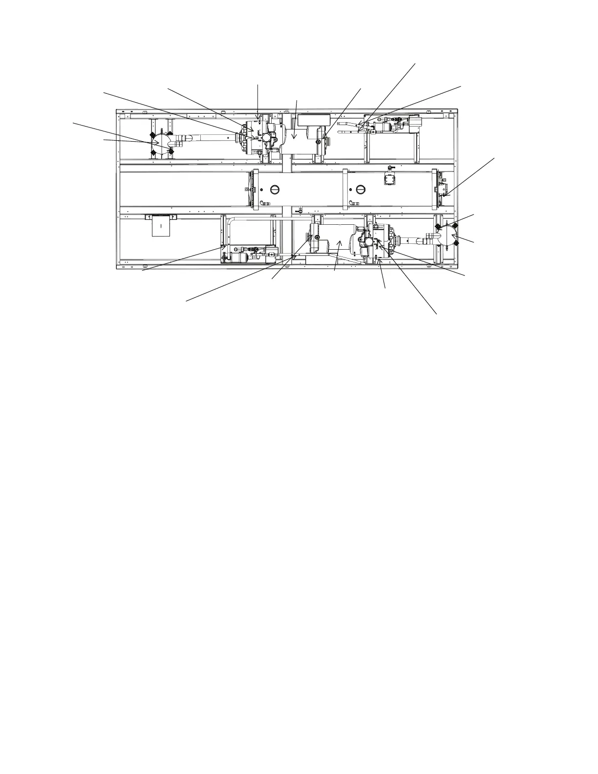
Fig. 58 — Transducer and Switch Locations
SERVICE
Economizer Assembly
Each circuit on the unit has an economizer assembly, which in-
cludes a brazed plate heat exchanger, EXVs, and other compo-
nents. See Fig. 59.
Electronic Expansion Valve
See Fig. 60 for a cutaway view of the EXV. High-pressure liq-
uid refrigerant enters the valve through the top. As refrigerant
passes through the orifice, pressure drops and refrigerant
changes to a 2-phase condition (liquid and vapor). The elec-
tronic expansion valve operates through electronically con-
trolled activation of a stepper motor. The stepper motor stays in
position unless power pulses initiate the two discrete sets of
motor stator windings for rotation in either direction. The di-
rection depends on the phase relationship of the power pulses.
The motor directly operates the spindle, which has rotating
movements that are transformed into linear motion by the
transmission in the cage assembly. The valve cone is a V-port
type which includes a positive shut-off when closed. The large
number of steps and long stroke results in very accurate control
of the refrigerant flow. The stepper motor has either 3810
(main) or 2625 (economizer) steps.
MAIN EXV CONTROL
The main EXV is controlled by the SIOB (J17-STPR1). Each
circuit has thermistors located in the compressor discharge
(DGT), compressor motor cavity (SGT) and liquid line leaving
the condenser (LIQT). Each circuit also has a DPT, SPT, and
LPT. All the pressure readings as measured by the transducers
are converted to saturated temperatures. Liquid pressure trans-
ducer (LPT) is converted to saturated liquid temperature (SLT).
The main control logic for the EXV uses liquid line subcool-
ing, which is the difference between the liquid line saturation
temperature and the liquid line temperature, to control the
position of the EXV. The SIOB module controls the position of
the electronic expansion valve stepper motor to maintain the
subcooling set point. The EXV control logic has several over-
rides, which are also used to control the position of the EXV.
• Normal Mode (SUBCOOL)
• Low Discharge Superheat (DSH)
• Low Suction Pressure (SPMIN)
• Maximum Suction Pressure (SPMAX)
• EXV Start (START)
To view EXV overrides: Main Menu
Maintenance Menu
EXV Control or Main Menu
Maintenance Menu
EXVECO Control.
Normal Mode (SUBCOOL)
This is the normal mode of operation of the EXV. Based on the
operating condition and loading of the compressor, the control
calculates an optimal subcooling setting to maximize the sys-
tem efficiency. The controls accordingly adjust the EXV open-
ing to meet this calculated subcooling setting. The range of the
subcooling setting can be altered by using the Network Service
Tool in the Configuration
EXV_CFG table.
Low Discharge Superheat (DSH)
This mode is disabled for 100 sec after the start of the circuit.
Control enters this mode when DSH is below 12°F (
–11.1°C).
The control attempts to drive DSH above 15°F (–9.4°C) by
closing the EXV. In this mode the setpoint is modified and
driven to a value that supports a higher DSH value upon exit of
the mode. This prevents mode cycling. Mode is exited when
the DSH is greater than 18
°F (–7.8°C) or the average DSH is
within 1.25° (0.7°C) of 15°F (
–9.4°C) and the subcooling is
above the subcooling setpoint.
SUCTION PRESSURE
TRANSDUCER (SPT A)
OIL SEPARATOR (A)
OIL PRESSURE
TRANSDUCER (OPT A)
ECONOMIZER PRESSURE
TRANSDUCER (EPT A)
LIQUID PRESSURE
TRANSDUCER (LPT A)
EVAPORATOR (B)
COMPRESSOR (B)
DISCHARGE PRESSURE
TRANSDUCER (DPT A)
SUCTION PRESSURE
TRANSDUCER (SPT B)
OIL PRESSURE
TRANSDUCER (OPT B)
ECONOMIZER PRESSURE
TRANSDUCER (EPT B)
LIQUID PRESSURE
TRANSDUCER (LPT B)
DISCHARGE PRESSURE
TRANSDUCER (DPT B)
OIL LEVEL SWITCH
(OIL LS B)
EVAPORATOR (A)
COMPRESSOR (A)
HIGH PRESSURE
SWITCH (HPS B)
HIGH PRESSURE
SWITCH (HPS A)
EVAPORATOR FLOW
SWITCH (CWFS)
OIL SEPARATOR
(B)
OIL LEVEL SWITCH
(OIL LSA)
POWERBOX END
 Loading...


