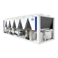
Do you have a question about the Carrier AquaForce 30XQ0502 and is the answer not in the manual?
Essential safety guidelines for unit installation personnel, emphasizing qualifications and procedures.
Details on safety aspects related to pressurized components within the unit, referencing specific sections.
Guidelines for safe repair procedures, emphasizing adherence to standards and immediate fault correction.
Instructions for safely moving and positioning the unit, including lifting points and clearance requirements.
Electrical specifications, including power supply, current draw, and operating power for various 30XQ models.
Electrical characteristics of the compressors, including nominal and maximum current, and power factor.
Specifications for the required power supply voltage, frequency, and phase for the chillers.
Guidance on acceptable voltage phase imbalance limits to prevent warranty invalidation.
Information on power connection points and the function of disconnect switches for unit safety.
Guidelines for selecting appropriate wire sizes based on current and installation methods.
A table detailing minimum and maximum wire sections for electrical connections based on model.
Overview of the twin-screw compressor, its capacity control, and features.
Details on the high-pressure safety switches, their types, and reset procedures.
Basic maintenance procedures that can be performed by the user, including visual checks and cleaning.
Maintenance tasks requiring specific technical skills, including electrical and hydronic checks.
Advanced maintenance operations performed by manufacturer or authorized agents, like component replacement.
Torque values for tightening main electrical connections, ensuring secure and safe electrical contact.
Procedures for cleaning air side heat exchanger coils to maintain performance and lifespan.
Maintenance procedures for the compressor, including oil separator and filter checks.
| Model | 30XQ0502 |
|---|---|
| Category | Chiller |
| Compressor Type | Scroll |
| Refrigerant | R-410A |
| Power Supply | 400V/50Hz/3Ph |
| Operating Range | -10 to 46 °C |


