EasyManua.ls Logo

Carrier 30RBP 400 User Manual

Carrier 30RBP 400
70 pages
To Next Page IconTo Next Page
Page #1 background imageLoading...
Page #1 background image
INSTALLATION, OPERATION AND
MAINTENANCE INSTRUCTIONS
Air-Cooled Liquid Chillers
30RBM 160-520
30RBP 160-520
Translation of the original document 23539, 10.2016
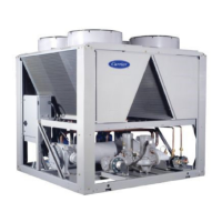
Unit with low noise level option
Nominal cooling capacity 164 - 528 kW 50 Hz
Unit with low noise level option

Table of Contents

Question and Answer IconNeed help?

Do you have a question about the Carrier 30RBP 400 and is the answer not in the manual?

Carrier 30RBP 400 Specifications

General IconGeneral
Model30RBP 400
CategoryChiller
Cooling Capacity400 tons
Refrigerant TypeR-134a
Compressor TypeScrew
Power Supply460V/3/60Hz

Summary

INTRODUCTION

Safety considerations related to protection devices

Safety notes on protecting unit components from damage or obstruction.

Refrigerant safety considerations

Installation safety considerations

Repair safety considerations

HANDLING AND POSITIONING

PHYSICAL AND ELECTRICAL DATA FOR THE UNITS

Electrical data 30RBM 160-520

Electrical data 30RBP 160-520

Electrical data for the hydronic module

Electrical data notes for the compressors

ELECTRICAL CONNECTION

Power supply

Requirements and specifications for the unit's main power supply.

Field control wiring

APPLICATION DATA

Water type heat exchanger water flow rate

Pressure drop curves for the water type heat exchanger and standard water inlet/outlet piping

WATER CONNECTIONS

Operating precautions and recommendations

Key checks and recommendations before connecting the hydronic circuits.

Hydronic connections

Cavitation protection (with hydronic option)

Frost protection

NOMINAL SYSTEM WATER FLOW RATE CONTROL

Units with hydronic module and fixed speed pump

Units with hydronic module and variable speed pump - Pressure differential control

Units with hydronic module and variable speed pump - Temperature differential control

Units with hydronic module and variable speed pump - Setting a fixed flow rate for the system

Pump pressure/flow rate curves

Available static system pressure

SYSTEM START-UP

Checks before system start-up

Detailed pre-start checks for the entire system and unit.

Commissioning

Steps for commissioning the unit, including safety device checks.

Essential points to check

Compressors

Key checks for compressors, hydraulics, and refrigerant charge.

MAIN COMPONENTS OF THE UNIT AND OPERATING CHARACTERISTICS

Fans

Water type heat exchanger

Variable frequency drive

Variable speed ventilation

Fan motor electrical protection

Installation and operation of the heat recovery with desuperheater option

Installation

Operating limits

Control configuration with the desuperheater option

Operation of 2 Master/Slave units (Option 58)

Brine option (Options 5B and 6B)

Units with variable operating pressure fans (Option 12)

Power factor correction (Option 231)

DX Free Cooling option (Options 118A and 118B)

Operation

STANDARD MAINTENANCE

Level 1 maintenance

Simple maintenance tasks that can be performed by the user.

Level 2 maintenance

More advanced maintenance requiring specialized expertise.

Level 3 maintenance

Tightening of the electrical connections

Tightening torques for the main fastenings

Air-cooled exchanger

Refrigerant volume

Power factor correction

FINAL SHUTDOWN

Recommendations for disassembly

Guidance on disassembling components for recycling or disposal.

Fluids to be recovered for treatment

Identification of fluids that require proper recovery and treatment.

UNIT START-UP CHECKLIST FOR INSTALLERS PRIOR TO CONTACTING THE MANUFACTURER

Related product manuals