Do you have a question about the Carrier 42CJR018-723 and is the answer not in the manual?
Technical specifications for specific indoor/outdoor unit models.
Technical specifications for specific indoor/outdoor unit models.
Technical specifications for specific indoor/outdoor unit models.
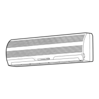
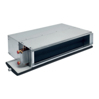
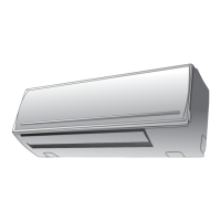
Construction details and dimensions of the indoor unit.
Construction details and dimensions of outdoor units.
Construction details and dimensions of specific outdoor units.
Construction details and dimensions of a specific outdoor unit.
Construction details and dimensions of a specific outdoor unit.
Wiring diagram for specific indoor/outdoor unit models.
Wiring diagram for specific indoor/outdoor unit models.
Wiring diagram for specific indoor/outdoor unit models.
Wiring diagram for specific indoor/outdoor unit models.
Electrical components and specifications for indoor units.
Electrical components and specifications for specific indoor units.
Electrical components and specifications for specific outdoor units.
Electrical components and specifications for specific outdoor units.
Electrical components and specifications for specific outdoor units.
Refrigeration cycle diagram for specific models.
Refrigeration cycle diagram for specific models.
Refrigeration cycle diagram for specific models.
Refrigeration cycle diagram for specific models.
Refrigeration cycle diagram for specific models.
Control block diagram for specific models.
Control block diagram for specific models.
Overview of control logic between indoor and outdoor units.
Detailed circuit operations for various modes.
Control for preventing excessive temperature rise.
Control to prevent indoor heat exchanger freezing.
Operation sequence for defrosting in heating mode.
Functionality and setting for restart after power failure.
Indicator for filter cleaning and reset procedure.
Important safety precautions before and during installation.
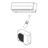
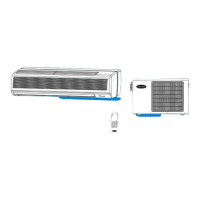
Visual guide for installing indoor and outdoor units.
Procedures and parts for unit installation.
Specific installation steps for the indoor unit.
Specific installation steps for the outdoor unit.
Procedure for setting remote control selector switches.
Additional procedures like gas leak test and test operation.
Steps to follow for troubleshooting issues.
Essential checks before diagnosing faults.
Initial fault assessment based on symptoms and lamps.
Using the remote for fault code diagnosis.
Flowcharts for diagnosing faulty components.
Specific troubleshooting steps for indoor unit issues.
Troubleshooting wiring and signal issues.
Procedures for checking and troubleshooting the P.C. board.
Steps to diagnose remote control issues.
Procedures for replacing indoor unit parts.
Procedures for replacing parts of specific outdoor units.
Procedures for replacing parts of a specific outdoor unit.
Procedures for replacing parts of a specific outdoor unit.
Procedures for replacing parts of a specific outdoor unit.
Exploded view and parts list for indoor unit components.
Detailed exploded view and parts list for the indoor unit.
Exploded view and parts list for specific outdoor units.
Exploded view and parts list for a specific outdoor unit.
Exploded view and parts list for a specific outdoor unit.
Exploded view and parts list for a specific outdoor unit.
Exploded view and parts list for a specific outdoor unit.
| Model | 42CJR018-723 |
|---|---|
| Refrigerant | R-410A |
| Phase | 1 |
| Frequency | 60 Hz |
| Cooling Capacity | 18000 BTU/h |
| Voltage | 208/230V |