42HQE009/012/018/022-38YE009/012/018/022
GB - 4
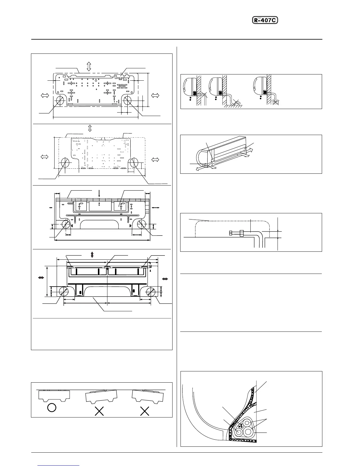
Drilling a hole and mounting installation plate
Installation Plate and Its Dimension (mm)
42HQE009
42HQE012
42HQE018
42HQE022
1.Fix the installation plate.
1.Install the installation plate horizontally on structural parts in
the wall with the spaces provided around the plate.
2.
In case of brick, concrete or similar type walls, make 6 mm Ø, holes
in the wall. Insert clip anchors for appropriate mounting screws.
3.Fix the installation plate on the wall.
Installation plate
2.Drilling a hole.
1.As diagram above determine the pipe hole position using
the installation plate, drill the pipe hole(Ø 65mm) so it slants
slightly downward.
2.Always use a wall hole conduit when piercing metal lath, ply
wood or metal plate.
Connective Pipe and Drainage Installation
Drainage
1. Run the drain hose sloping downward. Do not install the drain
hose as illustrated below.
2. When connection extension drain hose, insulate the
connecting part of extension drain hose with a shield pipe
Connective pipe
1. For the left-hand and right-hand piping, remove the rear plate
bushing from the left side of the rear plate.
Explain to clients that the pipe cover must be kept as it may be
used when relocate the air conditioner to any other place.
2. For the left-hand and rear-left-hand piping, install the piping as
shown. Bend the connective pipe to be laid at 43 mm height
or less from the wall.
3. Fix the end of the connective pipe.
(Refer to Tightening Connection in REFRIGRANT PIPING
CONNECTION).
CAUTION:
• Connect the indoor unit first then the outdoor unit and bend and
arrange the pipe carefully.
• Do not allow the piping to let out from the back of the indoor
unit.
• Be careful not to let the drain hose slack.
• Insulate both of the auxiliary piping.
• Banding the drain hose under the auxiliary pipe.
• Do not allow the piping to let out from the back of the indoor
unit.
Piping and bandaging
Wind the connective cable, drain hose and wiring with tape
securely, evenly as shown below.
• Because the condensed water from rare of the indoor unit is
gathered in ponding box and is piped out of room. Do not put
anything else in the box.
Indoor unit installation
22
Indoor unit outline
Installation plate
150 mm or more to ceiling
120 mm or more to wall
Left refrigerant pipe hole
20
30
250
45
70
750
65
65
280
65
65
50
50
815
42
65
65
49
50
90
906
55
50
1800
432
432
108
22
115
115
465
465
95 95
50 58
50 58
Right refrigerant pipe hole
Rear-left pipe hole
Rear-right pipe hole
Hooked part
Pipe hole
Do not form
a rise
Do not put
the hose end
into water
Pipe cover
Pipe holder
Left piping
Left back piping
Right back piping
Right piping
.
.
.
.
.
.
.
.
.
.
.
.
.
.
.
.
.
.
.
.
.
.
.
.
.
.
.
.
.
.
.
.
.
.
.
.
.
.
.
.
.
.
.
.
.
.
.
.
.
.
.
.
.
.
.
.
.
.
.
.
.
.
.
.
.
.
.
.
.
.
.
.
.
.
.
.
.
.
.
.
.
.
.
.
.
.
.
.
.
.
.
.
.
.
.
.
.
.
.
.
.
.
.
.
.
.
.
.
.
.
.
.
.
.
.
.
.
.
.
.
.
.
.
.
.
.
.
.
.
.
.
.
.
.
.
.
.
.
.
.
.
.
.
.
.
.
.
.
.
.
.
.
.
.
.
.
43
Indoor unit
outline
Connective
pipe
Indoor unit
Connective pipe
Ponding box
Pipe room
Wrapping belt
Drain hose
.
.
.
.
.
.
.
.
.
.
.
.
.
.
.
.
.
.
.
.
.
.
.
.
.
.
.
.
.
..
.
 Loading...