Do you have a question about the Carrier 42HQG024 and is the answer not in the manual?
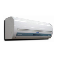
Diagram illustrating the components and airflow of the split system.
Explanation of buttons and their functions on the remote controller.
Visual guide to the remote control's LCD screen and its indicators.
Explanation of the various timer functions (OFF, ON, combination, sleep).
Operation and determination logic for the dry mode.
How the unit automatically selects cooling or heating based on room temperature.
Time delay mechanisms protecting the compressor and unit operations.
Wiring diagram for specific indoor unit models.
Wiring diagram for specific heat pump indoor unit models.
Functional overview of the electrical system and component interactions.
Detailed schematic of the main control printed circuit board.
Procedure for checking fan motor insulation resistance.
Method for checking compressor motor windings and overload protector.
Step-by-step guide for disassembling the indoor unit.
| Refrigerant | R410A |
|---|---|
| Voltage | 208/230 V |
| Phase | 1 |
| Compressor Type | Rotary |
| Type | Split |
| Cooling Capacity | 24000 BTU/h |
| Heating Capacity | 24000 BTU/h |
| Energy Efficiency Ratio (EER) | 11.0 |
| Power Supply | 60 Hz |
| Outdoor Unit Weight | 99 lbs |