4
installation manual
Evaluate the ceiling construction and please install with Ø10
hanging screw bolts.
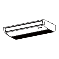
5.2 Install the main body
Fig. 5-2
Fig.5-8
Fig.5-7
STEEL ROOF BEAM STRUCTRUE
Hanging screw bolt
Hanging
bolts
Supporting
angle steel
Install and use directly the supporting angle steel.
Please Refer to Fig.5-3 and Fig.5-4 for the hanging screw
bolts distance
The handling to the ceiling varies from the constructions,
consult the construction person for the specific condition.
Do keep the ceiling flat. Consolidate the roof beam to avoid
possible vibration.
1 Installing Ø10 hanging screw bolts. (4 bolts)
2 Install the indoor unit.
After the selection of installation location, position the refrigerant
pipes, drain pipes,indoor & outdoor wires to the connection
places before hanging up the machine.
Cut off the roof beam.
Strengthen the place that has been cut off, and
consolidatethe roof beam.
The installation of hanging screw bolts.
Fig.5-3
Fig.5-4
Fig.5-5
Fig.5-6
Fig.5-7
WOODEN CONSTRUCTION
NEW CONCRETE BRICKS
FOR ORIGINAL CONCRETE BRICKS
Steel bar
Embedding screw bolt
(Pipe hanging and embedding screw bolt)
(Blade shape
insertion)
(Slide insertion)
Roof beam
Hanging screw bolts
Ceiling
Timber over the beam
Put the square timber traversely overthe roof beam, then install
the hanging screw bolts.
Inlaying or embedding the screw bolts.
Install the hanging hook with expansible bolt into the concrete
deep to 45~50mm to prevent loose.
Remove the side board and the grille. (Refer to Fig. 5-8)
Side board
Grille
Hanging arm
H a n g i n g
s c r e w b o l t
B
E. Connecting point of
refrigerant pipe
(D. gas side)
D. Connecting point of
refrigerant pipe
(E. Liquid side)
Drain point
C
D
Hook
 Loading...