3
installation manual
4. ATTACHED FITTINGS
Please check whether the following fittings are of full scope. If there are some spare fittings , please restore them carefull y .
There is no direct radiation from heat sources.
QUANTITY SHAPE NAME
5. Owner's manual
6. Installation manual
7. Remote controller manual
1. Remote controller
2. Remote controller holder
4. Alkaline dry batteries (AM4)
1
1
2
2
1
1
Remote controller & Its Holder
Others
3. Mounting screw(ST2.9×
10-C-H)
1
8. R22 Piston
(NOTE: This part must be used to
replace the defaut R410a throttle
piston when the unit is to match up
with a R22 CDU.)
1
Keep indoor unit, outdoor unit, power supply wiring and
transmission wiring at least 1 meter away from televisions
and radios. This is to prevent image interference and
noise in those electrical appliances. (Noise may be
generated depending on the conditions under which the
electric wave is generated, even if 1 meter is kept.)
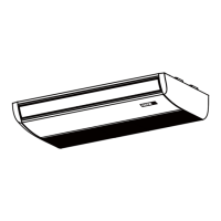
5. INDOOR UNIT INSTALLATION
5.1 Installation place
(Refer to Fig.5-1,Fig.5-2 and Table 5-1 for specification.)
The indoor unit should be installed in a location that meets
the following requirements:
CAUTION
Fig.5-1
≥35mm
≥1000mm
m m 5 3 ≥
m m 5
3
≥
There is enough room for installation and maintenance.
The ceiling is level, and its structure can endure the
weight of the indoor unit.
Th e outle t an d th e inle t ar e no t impeded , an d
outdoor air intrusion is minimal.
The air flow can reach throughout the room.
The connecting pipe and drainpipe could be routed
easil y .
There is no direct radiation from heat sources.
CANCEL
LOCK
SET TEMPERATURE(°C)
AUTO
COOL
DRY
HEAT
FAN
HIGH
MED
LOW
TEMP
MODE
SWING TIMER
RESET
ON/OFF
FAN
SPEED
VENT
ECONOMIC
RUNNING
 Loading...