70
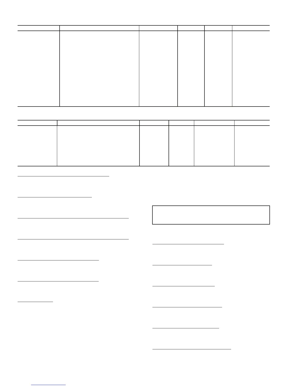
Table 81 — Alert Limit Configuration
Table 82 — Sensor Trim Configuration
Outdoor Air Temperature Sensor Trim (
OAT.T) — This vari-
able is used to adjust the outdoor air temperature sensor read-
ing. The sensor reading can be adjusted ± 10° F to match the
actual measured temperature.
Space Temperature Sensor Trim (
SPT.T) — This variable is
used to adjust the space temperature sensor reading. The sensor
reading can be adjusted ± 10° F to match the actual measured
temperature.
Circuit A Saturated Condenser Temperature Trim (
CTA.T) —
This variable is used to adjust the saturated condenser tempera-
ture sensor reading for circuit A. The sensor reading can be
adjusted ± 30° F to match the actual measured temperature.
Circuit B Saturated Condenser Temperature Trim (
CTB.T) —
This variable is used to adjust the saturated condenser tempera-
ture sensor reading for circuit B. The sensor reading can be
adjusted ± 30° F to match the actual measured temperature.
Suction Pressure Circuit A Trim (
SP.A.T) — This variable is
used to adjust the suction pressure sensor reading for circuit A.
The sensor reading can be adjusted ± 50 psig to match the actu-
al measured pressure.
Suction Pressure Circuit B Trim (
SP.B.T) — This variable is
used to adjust the suction pressure sensor reading for circuit B.
The sensor reading can be adjusted ± 50 psig to match the actu-
al measured pressure.
4 to 20 mA Inputs
— There are a number of 4 to 20 mA in-
puts which may be calibrated. These inputs are located in
Inputs
→
4-20. They are:
• SP.M.T — static pressure milliamp trim
• BP.M.T — building pressure milliamp trim
• OA.M.T — outside air cfm milliamp trim
• RA.M.T — return air cfm milliamp trim
• SA.M.T — supply air cfm milliamp trim
Discrete Switch Logic Configuration — The SW.LG
submenu is used to configure the normally open/normally closed
settings of switches and inputs. This is used when field-supplied
switches or input devices are used instead of Carrier devices. The
normally open or normally closed setting may be different on a
field-supplied device. These points are used to match the control
logic to the field-supplied device.
The defaults for this switch logic section will not normally
need changing. However, if a field-installed switch is used that
is different from the Carrier switch, these settings may need
adjustment.
Settings for switch logic are found at the local displays
under the Configuration
→
SW.LG submenu. See Table 83.
Filter Status Input — Clean (
FTS.L) — The filter status in-
put for clean filters is set for normally open. If a field-supplied
filter status switch is used that is normally closed for a clean
filter, change this variable to closed.
IGC Feedback — Off (
IGC.L) — The input for IGC feed-
back is set for normally open for off. If a field-supplied IGC
feedback switch is used that is normally closed for feedback
off, change this variable to closed.
Remote Switch — Off (
RMI.L) — The remote switch is set
for normally open when off. If a field-supplied control switch
is used that is normally closed for an off signal, change this
variable to closed.
Economizer Switch — No (
ECS.L) — The economizer
switch is set for normally open when low. If a field-supplied
economizer switch is used that is normally closed when low,
change this variable to closed.
Fan Status Switch — Off (
SFS.L) — The fan status switch
input is set for normally open for off. If a field-supplied fan
status switch is used that is normally closed, change this
variable to closed.
Demand Limit Switch 1 — Off (
DL1.L) — The demand
limit switch no. 1 input is set for normally open for off. If a
field-supplied demand limit switch is used that is normally
closed, change this variable to closed.
ITEM EXPANSION RANGE UNITS POINT DEFAULT
SP.L.O SPT lo alert limit/occ -10-245 dF SPLO 60
SP.H.O SPT hi alert limit/occ -10-245 dF SPHO 85
SP.L.U SPT lo alert limit/unocc -10-245 dF SPLU 45
SP.H.U SPT hi alert limit/unocc -10-245 dF SPHU 100
SA.L.O EDT lo alert limit/occ -40-245 dF SALO 40
SA.H.O EDT hi alert limit/occ -40-245 dF SAHO 100
SA.L.U EDT lo alert limit/unocc -40-245 dF SALU 40
SA.H.U EDT hi alert limit/unocc -40-245 dF SAHU 100
RA.L.O RAT lo alert limit/occ -40-245 dF RALO 60
RA.H.O RAT hi alert limit/occ -40-245 dF RAHO 90
RA.L.U RAT lo alert limit/unocc -40-245 dF RALU 40
RA.H.U RAT hi alert limit/unocc -40-245 dF RAHU 100
R.RH.L RARH low alert limit 0-100 % RRHL 0
R.RH.H RARH high alert limit 0-100 % RRHH 100
SP.L SP low alert limit 0-5 "H2O SPL 0
SP.H SP high alert limit 0-5 "H2O SPH 2
BP.L BP lo alert limit -0.25-0.25 "H2O BPL -0.25
BP.H BP high alert limit -0.25-0.25 "H2O BPH 0.25
IAQ.H IAQ high alert limit 0-5000 IAQH 1200
ITEM EXPANSION RANGE UNITS POINT DEFAULT
SAT.T Air Temp Lvg SF Trim -10 - 10 ^F SAT_TRIM 0
RAT.T RAT Trim -10 - 10 ^F RAT_TRIM 0
OAT.T OAT Trim -10 - 10 ^F OAT_TRIM 0
SPT.T SPT Trim -10 - 10 ^F SPT_TRIM 0
CTA.T Cir A Sat. Cond. Temp Trim -30 - 30 ^F SCTA_TRIM 0
CTB.T Cir B Sat. Cond. Temp Trim -30 - 30 ^F SCTB_TRIM 0
SP.A.T Suct.Press.Circ.A Trim -50 - 50 PSIG SPA_TRIM 0
SP.B.T Suct.Press.Circ.B Trim -50 - 50 PSIG SPB_TRIM 0
DP.A.T Dis.Press.Circ.A Trim -50 - 50 PSIG DPA_TRIM 0
DP.B.T Dis.Press.Circ.B Trim -50 - 50 PSIG DPB_TRIM 0
IMPORTANT: Many of the switch inputs to the con-
trol can be configured to operate as normally open or
normally closed.

 Loading...


