93
A407 (Smoke Purge Emergency Mode)
— Unit has been
placed in the fire pressurization mode by means of the External
command for pressurization (Inputs
→
FIRE
→
PURG).
If the smoke purge input on the CEM is energized, a smoke
purge mode occurs which flags an alarm. This mode attempts
to draw out smoke from the space after the emergency condi-
tion. Opening the economizer, closing the return air damper,
and turning on both the power exhaust and indoor fan will
evacuate smoke and bring in fresh air. Recovery is automatic
when the input is no longer on.
T408 (Dirty Air Filter)
— If no dirty filter switch is installed,
the switch will read “clean filter” all the time. Therefore the
dirty filter routine runs continuously and diagnoses the input.
Because of the different possible times it takes to generate
static pressure, this routine waits 2 minutes after the fan starts
before the dirty filter switch is monitored. If the dirty filter
switch reads “dirty filter” for 2 continuous minutes, an alert is
generated. No system action is taken. This is a reminder that it
is time to change the filters in the unit. Recovery from this alert
is through a clearing of all alarms (manual) or after the dirty
filter switch reads clean for 30 continuous seconds (automatic).
Because the Dirty Air Filter switch can be configured nor-
mally opened or closed, the switch might be open or closed.
The configuration for this switch input can be found at variable
Configuration
→
SW.LG
→
SFS.L. Verify that the configura-
tion is set correctly. Verify the wiring and filter status switch.
The hose should be connected to the low side of the switch.
This alert resets automatically. The dirty filter switch is enabled
at Configuration
→
UNIT
→
SENS
→
FLT.S.
A409 (Supply Fan Commanded On, Sensed Off Failure)
T409 (Supply Fan Commanded Off, Sensed On Failure)
A409 (Supply Fan Commanded On, Sensed Off Failure)
T409 (Supply Fan Commanded Off, Sensed On Failure) —
Both the alert and the alarm refer to the same failure. The only
difference between the alarm and alert is that in the case where
the supply fan status configuration to shut down the unit is set
to YES (Configuration
→
UNIT
→
SFS.S), the alarm will be
generated AND the unit will be shut down. It is possible to
configure Configuration
→
UNITS
→
FS.M to either a switch
or to monitor a 0.2-in. wg rise in duct pressure if the unit is
VAV with duct pressure control (IGV or VFD).
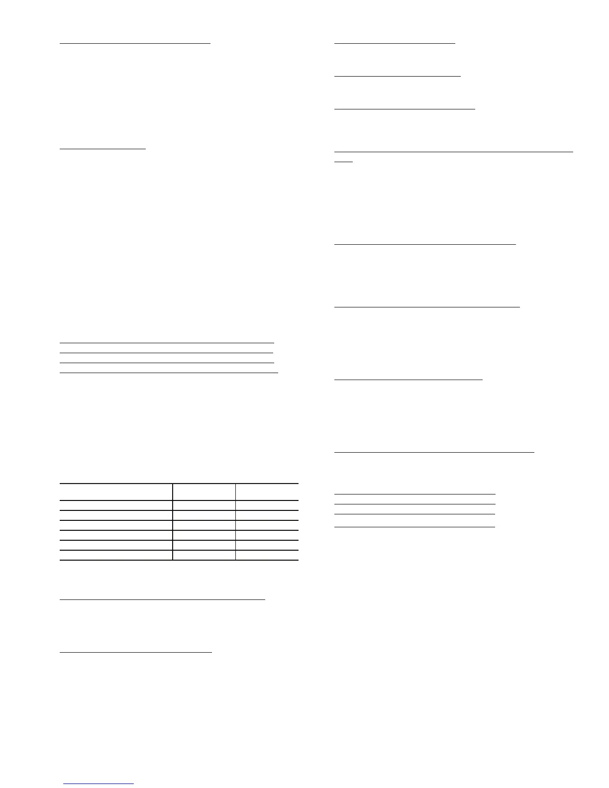
The timings for failure for both are the same and are
illustrated in the following table:
Recovery is manual. Reason for failure may be a broken fan
belt, failed fan relay or failed supply fan status switch.
T414 (Loss of Communication with Belimo Actuator
) — The
Belimo economizer motor is a digital controlled motor. The
ComfortLink™ control can monitor the status of the motor. If
there is a problem, this alert will occur. The control will attempt
to close the economizer dampers.
T414 (Belimo Actuator Direction Error)
— This alert occurs
when the economizer damper direction switch is in the wrong
position. The direction switch should be in the clockwise posi-
tion and the actuator should be mounted so that the CW face of
the actuator is accessible. Correct if necessary. This alert clears
automatically.
T414 (Belimo Actuator Failure)
— This alert occurs when the
commanded damper position is changing too rapidly. This alert
resets automatically.
T414 (Belimo Actuator Jammed)
— This alert occurs when
the control software has detected that the damper is stuck.
Check the mechanical actuation of the dampers.
T414 (Belimo Actuator Range Error)
— This alert occurs
when the economizer range of motion is less than 90 degrees.
Initiate economizer calibration (Service Test
→
INDP
→
E.CAL) using the Service Test menu.
T420 (R-W1 Jumper Must be Installed to Run Heat in Service
Test) — This alert occurs when a request for a heat output has
occurred yet the W1 input is not high. A jumper must be
installed between R and W1 when trying to test heat in Service
Test. The alert will clear when Service Test is exited or if
another Service Test mode is selected. Remove jumper when
done using Service Test if the unit is operating with a thermo-
stat. The jumper should only be left in place if the unit is
operating with a Space Temperature sensor.
T421 (Thermostat Y2 Input On without Y1 On)
— This alert
occurs in Thermostat Mode when Y2 is energized and Y1 is
not. Verify thermostat and thermostat wiring. When Y2 turns
on, the software will behave as if Y1 and Y2 are both on. When
Y2 turns off, the software will behave as if Y1 and Y2 are both
Off. This alert resets automatically when Y1 is turned on.
T422 (Thermostat W2 Input On without W1 On)
— This alert
occurs in Thermostat Mode when W2 is energized and W1 is
not. Verify thermostat and thermostat wiring. When W2 turns
on, the software will behave as if W1 and W2 are both on.
When W2 turns off, the software will behave as if W1 and W2
are both off. This alert resets automatically when W1 is turned
on.
T423 (Thermostat Y and W Inputs On)
— This alert occurs in
Thermostat Mode when Y1 or Y2 is energized simultaneously
with W1 or W2. Verify thermostat and thermostat wiring. The
software will enter either the cooling or heating mode depend-
ing upon which input turned on first. This alert resets automati-
cally when Y1 and Y2 are not on simultaneously with W1 and
W2.
T424 (Thermostat G Input Off On a Cooling Call)
— This
alert occurs in Thermostat Mode when the fan is not requested
(G = ON) during cooling (Y1 or Y2 = ON). Verify thermostat
and thermostat wiring.
T500 (Current Sensor Board Failure – A1)
T501 (Current Sensor Board Failure – A2)
T502 (Current Sensor Board Failure – B1)
T503 (Current Sensor Board Failure – B2) — Alert codes 500,
501, 502, and 503 are for compressors A1, A2, B1, and B2
respectively. These alerts occur when the output of the current
sensor (CS) is a constant high value. These alerts reset auto-
matically. If the problem cannot be resolved and the CS board
must be replaced, the CS board can be temporarily disabled
while securing a replaced board. A CS board is disabled by set-
ting Configuration
→
COOL
→
CS.A1, CS.A2, CS.B1 or
CS.B2 to Disable.
If the current sensor board malfunctions or is not properly
connected to its assigned digital input, an alert will be generat-
ed. It takes 2 to 4 seconds to log the alert. If the alert is logged,
it stays for a minimum of 15 seconds to provide the application
a reasonable time to catch the failure. Compressors will be not
be inhibited by this failure. Recovery is automatic. Reason for
failure may be a faulty current sensor board, incorrect wiring,
or a damaged input on the MBB control board.
UNIT TYPE/MODE
MINIMUM ON
TIME
MINIMUM OFF
TIME
CV (no gas heat) 30 seconds 1 minute
CV (gas heat) 2 minutes 4 minutes
VAV (IGV/no gas heat) 2 minutes 4 minutes
VAV (VFD/no gas heat) 1 minute 1 minute
VAV (IGV/gas heat) 4 minutes 4 minutes
VAV (VFD/gas heat) 3 minutes 4 minutes

 Loading...


