OPTIONAL PARABLADE ECONOMIZER — The op-
tional PARABLADE economizer hood assembly is pack-
aged and shipped in the filter section. Damper blades and
control boards are installed at the factory and the econo-
mizer is shipped in the vertical discharge position.
NOTE: Horizontal discharge block-off plate is shipped with
the air hood package. The PARABLADE economizer can
only be used for vertical discharge applications. Discard this
plate.
Assembly
1. Determine if ventilation air is required in building. If so,
determine minimum amount to be supplied by each unit
and record quantity of ventilation air needed for use in
Step 5.
2. Remove filter access panel by raising panel and swinging
panel outward. Panel is now disengaged from track and
can be removed. No tools are required to remove filter
access panel. Remove outdoor-air opening panel. Save
panels and screws. See Fig. 17.
3. Assemble outdoor-air hood top and side plates as shown
in Fig. 18. Install seal strips on hood top and sides. Put
aside screen retainer and retainer screw for later assem-
bly. Do not attach hood to unit at this time.
4. Insert economizer plug into economizer harness. Re-
move tape from barometric relief damper. See Fig. 26.
5. If ventilation air is not required, proceed to Step 6. If ven-
tilation air is required, perform the following:
a. Make sure the factory-installed jumper is in place across
terminals P and P1 on the economizer logic module.
T and T1 should be disconnected during adjustment.
b. The 2 potentiometers with slots for adjustment are lo-
cated on the face of the economizer logic module. Turn
the lower potentiometer fully clockwise. The dampers
should be fully closed. Turn the potentiometer gradu-
ally counterclockwise until the desired position is reached.
c. Connect T and T1 to the 24-v power supply.
d. After installation is complete, calculate the minimum
airflow across the economizer. To calculate the mini-
mum airflow, the following data is needed: total cfm
(cfm
3
), temperature of the total cfm (T
3
), temperature
of the return air (T
2
), and temperature of the entering
outside air (T
1
). Cfm
1
is the outside air (minimum)
cfm.
Insert the data into the following equations:
T
1
(cfm
1
)+T
2
(cfm
2
)
=T
3
cfm
3
cfm
2
= (cfm
3
− cfm
1
)
Therefore:
T
1
(cfm
1
)+T
2
(cfm
3
− cfm
1
)
=T
3
cfm
3
Further derivation reveals the following formula for
airflow:
(T
3
−T
2
) cfm
3
cfm
1
=
(T
1
−T
2
)
Use this equation to determine cfm
1
, which is the mini-
mum airflow across the economizer.
If cfm
1
does not match the desired minimum airflow
from Step 1, readjust the minimum position setting screw.
Fig. 25 — Varislide™ Economizer Barometric Relief
Damper Characteristics
LEGEND
OAT — Outdoor-Air Thermostat
NOTE: See unit wiring diagram for details.
Fig. 24 — Wiring Connections for Outdoor-Air
Thermostat
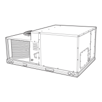
Fig. 26 — PARABLADE Economizer Installed
in Unit
16
 Loading...