EasyManua.ls Logo

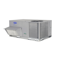
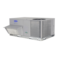
Carrier 50HCQ User Manual

Carrier 50HCQ
56 pages
To Next Page IconTo Next Page
Page #1 background imageLoading...
Page #1 background image
1
Installation Instructions
50HCQ
WeatherMaster
R
Series
Single Package Rooftop
Heat Pump
with Puronr (R-410A) Refrigerant
Sizes 07, 08, 09
NOTE: Read the entire instruction manual before starting
the installation
TABLE OF CONTENTS
SAFETY CONSIDERATIONS 2....................
Rated Indoor Airflow (cfm) 3.....................
REFRIGERATION SYSTEM COMPONENTS 8.......
INSTALLATION 10..............................
Jobsite Survey 10...............................
Step 1 − Plan for Unit Location 10.................
Roof Mount 10..............................
Step 2 − Plan for Sequence of Unit Installation 10.....
Curb−Mounted Installation 10..................
Pad−Mounted Installation 10...................
Frame−Mouned Installation 10.................
Step 3 − Inspect Unit 10..........................
Step 4 − Provide Unit Support 10..................
Roof Curb Mount 10.........................
Slab Mount (Horizontal Units Only) 11..........
Alternate Unit Support 11.....................
Step 5 − Field Fabricate Ductwork 13...............
For Units with Accessory Electric Heaters 13.....
Step 6 − Rig and Place Unit 13....................
Positioning on Curb 13.......................
Step 7 − Convert to Horizontal & Connect Ductwork 14.
Step 8 − Install Outside Air Hood 15...............
Economizer and Two Position Damper Hood
Package Removal and Setup − Factory Option 15..
Economizer Hood and Two−Position Hood 15.....
Step 9 − Install External Condensate Trap and Line 16...
Step 10 − Make Electrical Connections 16...........
Field Power Supply 16........................
Units with Factory−Installed
Non−Fused Disconnect 17.....................
Units without Factory−Installed
Non−Fused Disconnect 18.....................
Convenience Outlets 18.......................
Factory Option Thru−Base Connections 20.......
Units without Thru−Base Connections 20.........
Field Control Wiring 20.......................
Thermostat 20...............................
Central Terminal Board 20......................
Commercial Defrost Control 21..................
Unit without Thru−Base Connection Kit 23.......
Heat Anticipator Settings 23...................
Electric Heaters 23..............................
Single Point Boxes and Supplementary Fuses 24.....
Single Point Boxes without Fuses 24..............
Low−Voltage Control Connections 24.............
EconoMi$er X (Factory−Installed Option) 24.........
Staged Air Volume (SAVt) with
Variable Frequency Drive (Factory−Installed Option) 24
PremierLinkt Controller (Factory Option) 25........
Supply Air Temperature (SAT) Sensor 27.........
Outdoor Air Temperature (OAT) Sensor 27.......
EconoMi$er2 27.............................
Field Connections 27..........................
Space Sensors 30............................
Connect Thermostat 30.......................
Configure the Unit for Thermostat Mode 30......
Economizer Controls 31........................
Indoor Air Quality (CO
2
sensor) 31.............
Outdoor Air Quality Sensor 31.................
Smoke Detector/Fire Shutdown (FSD) 32.........
Filter Status Switch 32........................
Supply Fan Status Switch 32...................
Remote Occupied Switch 32...................
Power Exhaust (output) 33.....................
CCN Communication Bus 33..................
RTU Open Controller System 34...................
Supply Air Temperature (SAT) Sensor 36.........
Outdoor Air Temperature (OAT) Sensor 36.......
EconoMi$er2 36.............................

Table of Contents

Question and Answer IconNeed help?

Do you have a question about the Carrier 50HCQ and is the answer not in the manual?

Carrier 50HCQ Specifications

General IconGeneral
BrandCarrier
Model50HCQ
CategoryHeat Pump
LanguageEnglish

Summary

Safety Considerations

Warning and Caution Statements

Groups electrical, unit operation, personal injury, environmental, and cut hazard warnings.

Rated Indoor Airflow

Refrigeration System Components

Reversing Valve and Check Valve Position

Details the positions of reversing and check valves in different modes.

Refrigerant System Pressure Access Ports

Explains the location and type of refrigerant access ports.

Installation

Jobsite Survey

Checklist for site assessment before unit installation.

Step 1 - Plan for Unit Location

Guidance on selecting an appropriate unit location considering clearances.

Step 2 - Plan for Sequence of Unit Installation

Recommended sequences for curb, pad, and frame-mounted installations.

Step 3 - Inspect Unit

Procedures for inspecting the unit for damage and verifying electrical data.

Step 4 - Provide Unit Support

Instructions for roof curb mounting and unit support.

Slab Mount and Alternate Unit Support

Instructions for slab mounting and alternative support methods.

Step 5 - Field Fabricate Ductwork

Guidelines for fabricating and installing field-supplied ductwork.

Step 6 - Rig and Place Unit

Procedures for safely rigging, lifting, and positioning the unit on its support.

Step 7 - Convert to Horizontal Ductwork

Instructions for converting the unit configuration to horizontal ductwork.

Step 8 - Install Outside Air Hood

Steps for assembling and installing the economizer or two-position damper hood.

Step 9 - Install External Condensate Trap and Line

Guidance on installing the condensate trap and drain line for proper drainage.

Step 10 - Make Electrical Connections

Detailed instructions for making field power supply connections.

Units Without Disconnect Option

Wiring instructions for units without a factory-installed disconnect.

Units with Factory-Installed Non-Fused Disconnect

Steps for installing the handle and shaft for the non-fused disconnect.

Units Without Factory-Installed Non-Fused Disconnect

Instructions for providing a separate disconnect switch per NEC.

Convenience Outlets

Installation details for factory-offered non-powered and unit-powered convenience outlets.

Field Control Wiring

Wiring requirements for external temperature controls.

Thermostat Installation

Guidance on selecting, locating, and wiring Carrier-approved thermostats.

Commercial Defrost Control

Reversing Valve Control

Explains how the reversing valve operates during cooling, heating, and defrost cycles.

Compressor Control

Details compressor operation based on thermostat commands for cooling and heating.

Auxiliary (Electric) Heat Control

Describes how auxiliary electric heaters are energized for heating and defrost.

Defrost Operation

Explains the time/temperature sequence for initiating and controlling the defrost cycle.

PremierLink™ Controller (Factory Option)

PremierLink™ Controller Overview

General description of the PremierLink controller and its capabilities.

Supply Air and Outdoor Air Temperature Sensors

Instructions for mounting and wiring the SAT and OAT sensors.

EconoMi$er2 Integration

How the PremierLink controller manages the EconoMi$er2 for outdoor air control.

Field Connections for PremierLink

Locations for making field connections for sensors and input devices to the controller.

Space Sensors and Thermostat Connections

Details on space sensors and thermostat wiring to the PremierLink controller.

Configure Unit for Thermostat Mode

Steps to reconfigure the controller from Sensor Mode to Thermostat Mode.

Economizer Controls

Indoor Air Quality (CO2) Sensor

Details on installing and wiring IAQ sensors for air quality monitoring.

Outdoor Air Quality Sensor

Details on installing and wiring OAQ sensors for air quality monitoring.

Space Relative Humidity Sensors

Notes that these sensors are not used with 50HCQ units.

Smoke Detector/Fire Shutdown (FSD)

Configuration and wiring for the smoke detector shutdown function.

Filter Status Switch

Installation and wiring for monitoring dirty filter status.

Supply Fan Status Switch

Installation and wiring for monitoring supply fan operation status.

Remote Occupied Switch

Wiring for a remote timeclock to override occupancy schedule.

Power Exhaust (output)

Connection details for the accessory Power Exhaust contactor.

CCN Communication Bus

Specifications and wiring for the Carrier Comfort Network communication bus.

RTU Open Controller System

RTU Open Controller Overview

Description of the RTU Open controller and its integration capabilities.

Supply Air and Outdoor Air Temperature Sensors

Instructions for mounting and wiring the SAT and OAT sensors.

EconoMi$er2 Integration

How the RTU Open controller manages the EconoMi$er2 for outdoor air control.

Field Connections for RTU Open

Locations for making field connections for sensors and input devices to the RTU Open controller.

Space Temperature and IAQ Sensor Connections

Details on connecting SPT and IAQ sensors to the RTU Open controller.

Outdoor Air Quality Sensor and Discrete Inputs

Wiring OAQ sensor and configuring discrete inputs like filter/fan status.

Communication Wiring and Protocols

General information on communication protocols and wiring for BAS integration.

Unit Start-Up Checklist

Pre-Start-Up Verification

Checklist of items to verify before initiating unit start-up.

Cooling Cycle Start-Up Procedures

Procedures for recording electrical, temperature, and pressure data during cooling.

Heating Cycle Start-Up Procedures

Procedures for recording electrical, temperature, and pressure data during heating.

General Start-Up Checks

Final checks including economizer settings and smoke detector verification.
Related product manuals