2
Step 2 — Field Fabricate Ductwork — On vertical
discharge units, secure all ducts to roof curb and building
structure. Do not connect ductwork to unit. For horizontal appli-
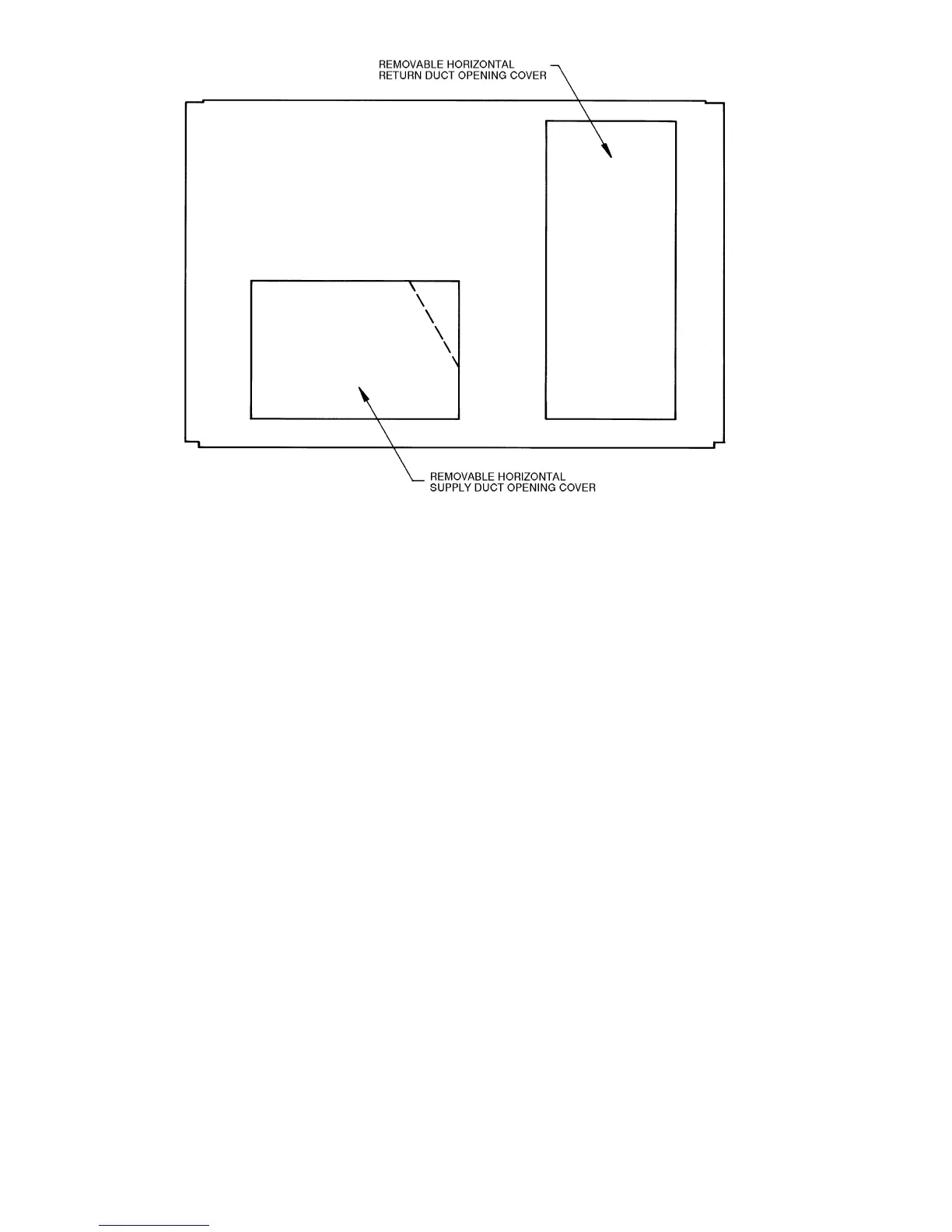
cations, field-supplied flanges should be attached to horizontal
discharge openings and all ductwork attached to the flanges. In-
sulate and weatherproof all external ductwork, joints, and roof
openings with counter flashing and mastic in accordance with
applicable codes.
Ducts passing through an unconditioned space must be
insulated and covered with a vapor barrier.
If a plenum return is used on a vertical unit, the return
should be ducted through the roof deck to comply with applica-
ble fire codes.
A minimum clearance to combustibles is not required
around ductwork on vertical discharge units. On horizontal dis-
charge units, a minimum clearance of 1 in. is required for the
first 12 in. of ductwork. Cabinet return-air static pressure (a
negative condition) should not exceed 0.30 in. wg with econo-
mizer, or 0.45 in. wg without economizer.
Step 3 — Install Condensate Drain Line and
External Trap — Condensate drain connections are locat-
ed at the bottom and end of the unit. Unit discharge connec-
tions do not determine the use of drain connections;
either drain connection can be used in vertical or horizontal
applications.
When using the standard end drain connection, make sure
the plug (red) in the alternate bottom connection is tight before
installing the unit.
To use the bottom drain connection for a roof curb installa-
tion, relocate the factory-installed plug (red) from the bottom
connection to the end connection. See Fig. 4. The piping for the
condensate drain and external trap can be completed after the
unit is in place. The center drain plug looks like a star connec-
tion, however it can be removed with a
1
/
2
-in. socket drive
extension.
All units must have an external trap for condensate drain-
age. Install a trap at least 4-in. deep and protect against freeze-
up. If drain line is installed downstream from the external trap,
pitch the line away from the 50HJ unit at 1 in. per 10 ft of run.
Do not use a pipe size smaller than the unit connection (
3
/
4
in.).
See Fig. 5.
Fig. 1 — Horizontal Conversion Panels

 Loading...
