EasyManua.ls Logo

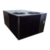
Carrier 50HC Series User Manual

Carrier 50HC Series
124 pages
To Next Page IconTo Next Page
Page #1 background imageLoading...
Page #1 background image
50HC
Single P ackage Rooft op Electric Co oling Unit
wit h Puron (R---410A) Refr igerant
3 to 12. 5 Nominal Tons (Sizes 04---14)
Service and Maintenance Instructions
TABLE OF CONTENTS
SAFETY CONSIDERATIONS 1....................
UNIT ARRANGEMENT AND ACCESS 2...........
SUPPLY FAN (BLOWER) SECTION 4..............
STAGED AIR VOLUME CONTROL --2 SPEED FAN
WITH VARIABLE FREQUENCY DRIVE (VFD) 7....
ADDITIONAL VARIABLE FREQUENCY DRIVE
(VFD) INSTALLATION AND TROUBLESHOOTING. 8
MOTOR 8......................................
COOLING 12...................................
THERMOSTATIC EXPANSION VALVE (TXV) 14....
PURONR (R --410A) REFRIGERANT 15.............
COOLING CHARGING CHARTS 17................
COMPRESSOR 21...............................
CONVENIENCE OUTLETS 24....................
SMOKE DETECTORS 25.........................
SENSOR AND CONTROLLER TESTS 29...........
PROTECTIVE DEVICES 32.......................
PREMIERLINK CONTROL 33...................
RTU--OPEN CONTROL SYSTEM 33................
SENSORY/ACCESSORY INSTALLATION 34........
ADDITIONAL RTU--OPEN INSTALLATION AND
TROUBLESHOOTING 34.........................
ECONOMIZER UNITS 36........................
PRE-- START--UP/START--UP 44....................
START--UP, GENERAL 45........................
START--UP, PREMIERLINK CONTROLS 46.......
START--UP, RTU--OPEN CONTROLS 46............
FASTENER TORQUE VALUES 47.................
APPENDIX I. MODEL NUMBER SIGNIFICANCE 48.
APPENDIX II. PHYSICAL DATA 49................
APPENDIX III. FAN PERFORMANCE 52...........
APPENDIX IV WIRING DIAGRAMS 71............
APPENDIX V. MOTORMASTER SENSOR
LOCATIONS 121................................
UNIT START-UP CHECKLIST 124.................
SAFETY CONSIDERAT I ONS
Installation and servicing of air-conditioning equipme nt
can be hazardous due to system pressure and electrical
compone nts. Only trained and qualified service personnel
should install, repair, or service air-conditioning
equipment. Untrained personnel can perform the basic
maintenance functions of replacing filters. Trained service
personnel should perform al l other operations.
When working on a ir-conditioning equipment, observe
precautions in the literature, tags and labels attached to
the unit, and other safety precautions that may apply.
Follow all safety codes. Wear safety glasses and work
gloves. Use quenc hing cloth for unbrazing operat ions.
Have fire extinguishers availabl e for all brazing and
unbrazing ope rations.
Read these instructions thoroughly and follow all
warnings or cautions attached to the unit. Consult local
building codes and National Electrical Code (NEC) for
special requirements.
Recognize safety information. This is the safety ALERT
symbol
. When you se e this symbol on the unit and i n
instructions or manuals, be aware of the potenti al for
physical injury hazards.
Understand the signal words DANGER, WARNING,and
CAUTION. These words are used with the safety--ALERT
symbol. DANGER indicates a hazardous situation which,
if not avoided, will result in death or severe personal
injury. WARNING indicates a hazardous situation which,
if not avoided, could result in death or personal injury.
CAUTION indicates a hazardous situation which, if not
avoide d, could result in minor to moderate injury or
product and property damage. NOTICE is used to address
practices not rela ted to physical injury. NOTE is used to
highlight suggestions which will result in enhanced
installation, reliability, or operation.

Table of Contents

Question and Answer IconNeed help?

Do you have a question about the Carrier 50HC Series and is the answer not in the manual?

Carrier 50HC Series Specifications

General IconGeneral
BrandCarrier
Model50HC Series
CategoryAir Conditioner
LanguageEnglish

Summary

SAFETY CONSIDERATIONS

Signal Word Definitions

Explains DANGER, WARNING, and CAUTION signal words.

UNIT ARRANGEMENT AND ACCESS

General Access Information

Provides general information on unit arrangement and access locations.

ROUTINE MAINTENANCE

Quarterly Inspection

Tasks for quarterly inspection and initial start-up.

Seasonal Maintenance

Tasks to be checked at the beginning of each season.

Air Conditioning Maintenance

Maintenance items for air conditioning components.

Economizer/Outside Air Damper Maintenance

Maintenance for economizer or outside air damper components.

Air Filters and Screens

Details on periodic replacement or cleaning of air filters and screens.

SUPPLY FAN (BLOWER) SECTION

Direct-Drive Supply Fan

Details about the direct-drive supply fan, including ECM motor.

ECM Motor Troubleshooting

Steps and checks for troubleshooting the X13 ECM motor.

ECM Motor Replacement

Detailed steps for replacing the X-13 ECM motor assembly.

SUPPLY FAN (BELT-DRIVE)

Belt Maintenance

Information on checking belt condition, tension, and adjustment.

Belt Replacement

Step-by-step procedure for replacing the V-belt.

Fan Speed Adjustment

Procedures for changing fan speed by adjusting pulleys.

STAGED AIR VOLUME CONTROL (VFD)

SAV System Operation

How the SAV system adjusts fan speed for ventilation, cooling, and heating.

VFD INSTALLATION AND TROUBLESHOOTING

Motor Replacement

Step-by-step procedure for replacing a belt-driven motor.

COOLING

Condenser Coil Cleaning

Recommendations for routine cleaning of condenser coils.

EVAPORATOR COIL CLEANING

THERMOSTATIC EXPANSION VALVE (TXV)

TXV Operation

Explanation of how the TXV operates to control refrigerant flow.

TXV Replacement

Step-by-step procedure for replacing the TXV.

Refrigerant Access Ports

Location and description of refrigerant system access ports.

PURON® (R--410A) REFRIGERANT

Refrigerant Charge Information

Information on where to find refrigerant charge amount and unit panel requirements.

Low-Charge Cooling

Using cooling charging charts and sub-cooling for charging.

Cooling Charging Chart Usage

Instructions on how to use cooling charging charts.

COMPRESSOR

Compressor Rotation Check

How to determine and ensure correct compressor rotation direction.

CONVENIENCE OUTLETS

Weatherproof Cover Installation

Instructions for installing a weatherproof cover for convenience outlets.

Outlet Types

Details for non-powered and unit-powered convenience outlets.

SMOKE DETECTORS

Smoke Detector System Overview

Overview of the smoke detector system and its primary function.

Smoke Detector Controller

Description of the smoke detector controller components and LEDs.

Smoke Detector Sensor

Description of the smoke detector sensor, its components, and operation.

Smoke Detector Installation

Steps to complete the installation of the return air smoke detector.

Smoke Detector Wiring & Response

Explains detector wiring and shutdown response.

SENSOR AND CONTROLLER TESTS

Sensor Alarm Test

Checks the sensor's ability to signal an alarm state using a test magnet.

Controller Alarm Test

Checks the controller's ability to initiate and indicate an alarm state.

Dirty Sensor Test

Indicates sensor's ability to compensate for environmental changes (dirtiness).

Remote Station Alarm Test

Checks the test/reset station's ability to initiate and indicate an alarm state.

DETECTOR CLEANING

Smoke Detector Cleaning Procedure

Instructions for cleaning the duct smoke sensor.

Detector Indicators

Explains the normal and alarm state indicators for the smoke detector.

Resetting Alarm/Trouble Conditions

Procedure for resetting alarm and trouble conditions.

TROUBLESHOOTING

Controller LED Troubleshooting

Checks for causes when controller LEDs indicate issues.

Sensor LED Troubleshooting

Checks for causes when sensor LEDs indicate issues.

PROTECTIVE DEVICES

Compressor Protection

Details on compressor protection mechanisms.

Evaporator Freeze Protection

Explanation of evaporator freeze protection.

Indoor Fan Motor Protection

Information on indoor fan motor protection devices.

PREMIERLINK™ CONTROL

RTU-OPEN Control System

Overview of the RTU-Open controller and its capabilities.

SENSORY/ACCESSORY INSTALLATION

ADDITIONAL RTU--OPEN INSTALLATION AND TROUBLESHOOTING

ECONOMIZER SYSTEMS

EconoMi$er IV Sensor Information

Summary and troubleshooting of EconoMi$er IV sensors.

Outdoor Dry Bulb Changeover

How outdoor dry bulb temperature controls economizer operation.

Differential Dry Bulb Control

Control mode using differential dry bulb sensors.

Outdoor Enthalpy Changeover

Control mode using outdoor enthalpy for economizer operation.

Differential Enthalpy Control

Control mode using differential enthalpy sensors for economizer.

IAQ Sensor Input

Using IAQ sensor for demand control ventilation.

Demand Control Ventilation (DCV)

Considerations for DCV when selecting equipment.

DCV Control Procedures

Procedures for checking DCV functions and positions.

PRE--START--UP/START--UP

START--UP, GENERAL

Unit Preparation

Ensures unit is installed correctly per instructions and codes.

Additional Installation Inspection

Inspecting field-installed accessories and RTU-OPEN alarms.

Compressor Rotation Verification

Determining correct compressor rotation direction.

Cooling Mode Start-Up

Steps for starting the unit in cooling mode.

START--UP, PREMIERLINK CONTROLS

PremierLink Setup Instructions

Refers to PremierLink setup and configuration instructions.

PremierLink System Check-Out

Steps for performing a system check-out.

START--UP, RTU--OPEN CONTROLS

RTU-Open Setup Instructions

Refers to RTU-Open controller setup and configuration manuals.

FASTENER TORQUE VALUES

APPENDIX I. MODEL NUMBER NOMENCLATURE

APPENDIX II. PHYSICAL DATA

APPENDIX III. FAN PERFORMANCE

X13 Motor Performance Data

Information on X13 multi-speed/torque motor performance.

APPENDIX IV. WIRING DIAGRAMS

APPENDIX V. MOTORMASTER SENSOR LOCATIONS

UNIT START-UP CHECKLIST

Related product manuals