27
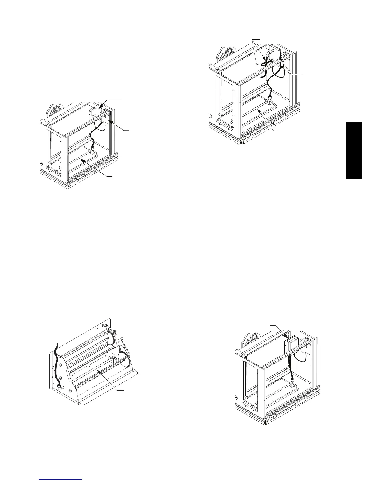
Return Air Smoke Detector Sensor without
Economizer: The sampling tube is located across the
return air opening on the unit basepan. See Fig. 34. The
holes in the sampling tube face downward, into the return
air stream. The sampling tube is connected through tubing
to the return air sensor t hat i s mounted on a bracket high
on the partition between return filter and controller
location. (T his sensor is shipped in a flat--mounting
location. Installation requires that this sensor be relocated
to its operating location a nd the tubing to the sampling
tube be connected. See installation steps below.)
*RA detector must be moved from shipping
position to operating position by installer
RETURN AIR DETECTOR
SAMPLING TUBE
RETURN AIR
DETECTOR MODULE
(Shipping position
shown)*
CONTROLLER
MODULE
C07307
Fig. 34 -- Typical Return Air Smoke Detector Location
Return Air Smoke Detector Sensor with Economizer:
The sampling tube is inserted through the side plates of
the e conomizer housing, placing it across the return air
opening on the unit basepan. See Fig. 35. The holes in the
sampling tube face downward, into the return air stream.
The sampling tube is connected using tubing to the return
air sensor mounted on a bracket high on the partition
between return filter and controller location. The sensor is
shipped in a flat--mounting location. Installation requires
the sensor be relocated to its operating location and the
tubing to the sampling tube be connected. See installation
steps below.
RETURN AIR
SAMPLING TUBE
C08129
Fig. 35 -- Return Air Sampling Tube Location
(View is reoriented to show opposite side for clarity.)
Completing Installation of Return Air Smoke
Detector:
SAMPLE TUBE
SCREWS
FLEXIBLE EXHAUST TUBES
C12049
Fig. 36 -- Return Air Smoke Detector Module
Shipping Position
Use the following steps to complete the installation of the
Return Air Smoke Detector.
1. Unscrew the two screws holding the Return Air
Sensor De tector plate. See Fig. 36. Save the screws.
2. Remove the Return Air Smoke Sensor Module and its
detector plate.
3. Rotate the detector plat e so the sensor i s facing out-
wards and the sampl ing tube conne ction is on the bot-
tom. See Fig. 37.
4. Screw the sensor and detector plate into its operating
position using screws from Step 1. Ensure the
sampling tube connect ion is on the bottom and the ex-
haust tube is on the top. See Fig. 37.
5. Connect the fle xible tube on the sampling inlet to the
sampling tube on the basepan.
6. For units with an economizer, the sampling tube is
integrated into the econom izer housing but
connecting the flexible tubing to the sampling tube is
the same.
RETURN AIR SENSOR
(Operating Position Shown)
C12050
Fig. 37 -- Return Air Sensor Operating Position
50HC

 Loading...
