INSTALLATION
1. Remove unit from shipping carton. Leave top shipping skid on
the unit as a spreader bar to prevent the rigging straps from
damaging the unit. If the wood skid is not available, use a
spreader bar of sufficient length to protect unit from damage.
2. Position the lifting bracket assembly around the base of the
unit. Be sure the strap does not twist.
3. Place each of the 4 metal lifting brackets into the rigging holds
in the composite pan.
4. Thread lifting bracket strapping around bottom perimeter of
unit as follows:
a. Open lever of tension buckle (ratchet type).
b. Feed strapping through tension buckle as shown in Fig. 8.
c. Pull strapping through tension buckle unit taut.
d. Snap lever down to lock strap in tension buckle. To release
strapping, squeeze safety latch, lift lever, and pull webbing
outward.
5. Tighten the tension buckle until it is taut. Lifting brackets
must be secure in the rigging holds.
6. Attach field-supplied clevis or hook of sufficient strength to
hole in the lifting bracket (See Fig. 9).
7. Attach the 2 safety straps directly to the clevis or hook at the
4 rigging brackets. DO NOT attach the safety straps to the
lifting brackets (See Fig. 9).
8. Position lifting point directly over the unit’s center of gravity.
9. Lift unit. When unit is directly over the roof curb, remove the
2 safety straps. Lower the equipment onto the roof curb.
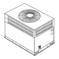
Fig. 2—50SZ024-030 Unit Dimensions
UNIT ELECTRICAL CHARACTERISTICS
UNIT WEIGHT
UNIT HEIGHT
IN. (MM)
”A”
CENTER OF GRAVITY
IN. (MM)
lb. kg X Y Z
50SZ024 208/230-1-60 343 156 39.02 (991) 20.0 (508) 19.3 (490) 17.6 (447)
50SZ030 208/230-1-60 366 166 41.02 (1042) 20.0 (508) 14.0 (356) 13.0 (330)
A05162
R
E
Q
U
I
R
E
D
C
L
E
A
R
A
N
C
E
F
O
R
O
P
E
R
A
T
I
O
N
A
ND
S
E
R
V
I
C
I
N
G
INCHES [mm]
EVAP. COIL ACCESS SIDE............................................................36.00 [914.0]
POWER ENTRY SIDE....................................................................42.00 [1066.8]
(EXCEPT FOR NEC REQUIREMENTS)
UNIT TOP .......................................................................................48.00 [1219.2]
SIDE OPPOSITE DUCTS ..............................................................36.00 [914.0]
DUCT PANEL .................................................................................12.00 [304.8]
*MINIMUM DISTANCES: IF UNIT IS PLACED LESS THAN 304.8 [12.00] FROM
WALL SYSTEM, THEN SYSTEM PERFORMANCE MAYBE COMPROMISE.
R
E
Q
U
I
R
E
D
C
L
E
A
R
A
N
C
E
T
O
C
O
M
B
U
S
T
I
B
L
E
M
A
TL
.
INCHES [mm]
TOP OF UNIT...................................................................................14.00 [355.6]
DUCT SIDE OF UNIT.........................................................................2.00 [50.8]
SIDE OPPOSITE DUCTS ................................................................14.00 [355.6]
BOTTOM OF UNIT .............................................................................0.50 [12.7]
N
E
C
.
R
E
Q
U
I
R
E
D
C
L
E
A
R
A
N
C
E
S
.
INCHES [mm]
BETWEEN UNITS, POWER ENTRY SIDE ....................................42.00 [1066.8]
UNIT AND UNGROUNDED SURFACES, POWER ENTRY SIDE .36.00 [914.0]
UNIT AND BLOCK OR CONCRETE WALLS AND OTHER
GROUNDED SURFACES, POWER ENTRY SIDE.........................42.00 [1066.8]
(
R
e
f
e
r
t
o
M
a
x
i
m
u
m
O
p
e
r
a
t
i
ng
C
l
ea
r
a
n
c
e
s
)
3
 Loading...