4
REQUIRED CLEARANCE FOR OPERATION AND SERVICING
INCHES [mm]
CONDENSER . COIL ACCESS SIDE..............................................30.00 [762.0]
POWER ENTRY SIDE....................................................................30.00 [762.0]
(EXCEPT FOR NEC REQUIREMENTS)
UNIT TOP .......................................................................................48.00 [1219.2]
SIDE OPPOSITE DUCTS ..............................................................30.00 [762.0]
LEGEND
NEC – National Electrical Code
NOTES:
1. Clearances must be maintained to prevent recirculation of air from outdoor-
fan discharge, with the exception of the condenser coil (36.00 in [914.0 mm]. A
removable fence or barricade requires no clearance.
2. Dimensions are in inches. Dimensions in [ ] are in millimeters.
REQUIRED CLEARANCE TO COMBUSTIBLE MATL.
INCHES [mm]
TOP OF UNIT.........................................................................................0
DUCT SIDE OF UNIT.............................................................................0
SIDE OPPOSITE DUCTS ......................................................................0
BOTTOM OF UNIT.................................................................................0
NEC. REQUIRED CLEARANCES.
INCHES [mm]
BETWEEN UNITS, POWER ENTRY SIDE ....................................42.00 [1066.8]
UNIT AND UNGROUNDED SURFACES, POWER ENTRY SIDE .36.00 [914.0]
UNIT AND BLOCK OR CONCRETE WALLS AND OTHER
GROUNDED SURFACES, POWER ENTRY SIDE.........................42.00 [1066.8]
27.80
[706.0]
3.50
[88.9]
2.11
[53.7]
13.89
[352.7]
13.89
[352.8]
4.63
[117.6]
13.88
[352.5]
5.44
[138.3]
DIMENSIONS IN [ ] ARE IN mm
50.98
[1295.0]
31.99
[812.5]
34.13
[867.0]
29.60
[751.8]
1.75 DIA.
[44.5]
2.72
69.0
1.0540 I.D. x .50 DEEP
[26.772 x 12.7]
1.20
[30.6]
21.61
[549.0]
0.88 DIA.
[22.2]
19.61
[498.1]
1.00
[25.4]
C00004
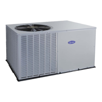
Fig. 4 -- Base Unit Dimensions, 50ZP060
UNIT ELECTRICAL CHARACTERISTICS
UNIT WEIGHT CENTER OF GRAVITY IN. (MM)
lb kg X Y Z
50ZP060 208/230--1--60, 208/230--3--60 344 156
355.6
(14.00)
508.0
(20.00)
355.6
(14.00)
50ZP

 Loading...